 | –≠–ª–µ–∫—Ç—Ä–æ–Ω–Ω—ã–π –∫–æ–º–ø–æ–Ω–µ–Ω—Ç: AM-145PIN | –°–∫–∞—á–∞—Ç—å:  PDF PDF  ZIP ZIP |
Features
n
2.5 dB Typical Midband Noise Figure
n
+19 dBm Typical Midband Output Power
n
+37 dBm Typical Midband Third Order Intercept
Description
M/A-COM's AM-145 is a coupler feedback amplifier with
high intercept and compression points. The use of coupler
feedback minimizes noise figure and current in a high
intercept amplifier. This amplifier is packaged in a TO-8
package. Due to the internal power dissipation the thermal
rise minimized. The ground plane on the PC board should
be configured to remove heat from under the package.
AM-145 are ideally suited for use where a high intercept,
high reliability amplifier is required.
High Performance Amplifier,
11 dB Gain, 10 - 1000 MHz
AM-/AM
C-145
TO-8-1
C-32
Absolute Maximum Ratings
1
1. Operation of this device above any one of these
parameters may cause permanent damage.
Parameter
Absolute Maximum
Max. Input Power
+10 dBm
V
bias
+15.75 V
Operating Temperature
-55∞C to +85∞C
Storage Temperature
-65∞C to +125∞C
V 3.00
High Performance Amplifier, 11 dB Gain, 10 - 1000 MHz
AM-/AMC-145
Specifications subject to change without notice.
n
North America: Tel. (800) 366-2266
n
Asia/Pacific: Tel.+81-44-844-8296, Fax +81-44-844-8298
n
Europe: Tel. +44 (1344) 869 595, Fax+44 (1344) 300 020
Visit www.macom.com for additional data sheets and product information.
V 3.00
2
Electrical Specifications
2,3
T
A
= -55∞C to +85∞C Case Temperature
Parameter
Test Conditions
Frequency
Units
Min.
Typ.
Max.
Gain
@ +25∞C
300 MHz
dB
10.1
10.7
11.3
Frequency Response
--
10-1000 MHz
dB
--
--
±1.0
Gain Variation with
Temperature
--
10-1000 MHz
dB
--
--
+1.0,-0.8
1 dB Compression
Output Power
10-1000 MHz
100-1000 MHz
dBm
dBm
+14
+17
--
--
--
--
Noise Figure
--
10-1000 MHz
10-500 MHz
dB
dB
--
--
--
--
5.5
4.0
Reverse Transmission
--
10-1000 MHz
dB
--
-13.5
-11.0
VSWR
--
10-1000 MHz
10-500 MHz
Ratio
Ratio
--
--
--
--
3:1
2:1
Output IP
2
Two-tone inputs up to +5 dBm
10-1000 MHz
dBm
+38
--
--
Output IP
3
Two-tone inputs up to +5 dBm
10-1000 MHz
dBm
+26
--
--
Vbias
--
--
VDC
+14.5
+15.0
+15.5
Ibias
Vbias = +15.0 VDC
--
mA
--
50
60
Power Dissipation
@15.0 V Bias
--
mW
--
750
--
S-Parameter Data
2. All specifications apply when operated at +15 VDC, with 50 ohms source and load impedance.
3. Heat Sinking: Operation at case temperature above 95∞C is not recommended. Heat sinking adequate to dissipate 0.8W must
be provided in use.
S11
S21
S12
S22
MAG
ANG
MAG
ANG
MAG
ANG
MAG
ANG
10
0.03
59.0
3.53
-160.8
0.21
-168.6
0.05
60.4
20
0.02
107.8
3.42
-171.3
0.22
-175.4
0.04
94.5
400
0.10
-18.6
3.50
131.8
0.22
134.3
0.11
-1.5
1000
0.21
162.9
3.51
55.5
0.23
69.3
0.18
-89.9
Frequency (MHz)
50
0.03
81.9
3.43
179.0
0.22
177.3
0.04
83.4
100
0.04
55.5
3.47
171.3
0.22
170.1
0.05
61.5
200
0.07
30.2
3.48
157.2
0.22
157.5
0.08
36.2
600
0.14
-64.1
3.54
106.9
0.23
111.8
0.14
-32.1
800
0.17
-115.9
3.49
82.1
0.23
90.6
0.16
-62.0
High Performance Amplifier, 11 dB Gain, 10 - 1000 MHz
AM-/AMC-145
Specifications subject to change without notice.
n
North America: Tel. (800) 366-2266
n
Asia/Pacific: Tel.+81-44-844-8296, Fax +81-44-844-8298
n
Europe: Tel. +44 (1344) 869 595, Fax+44 (1344) 300 020
Visit www.macom.com for additional data sheets and product information.
V 3.00
Typical Performance Curves
Noise Figure
3
1 dB Compression
Intermodulation Intercept
Gain vs. Frequency
VSWR vs. Frequency
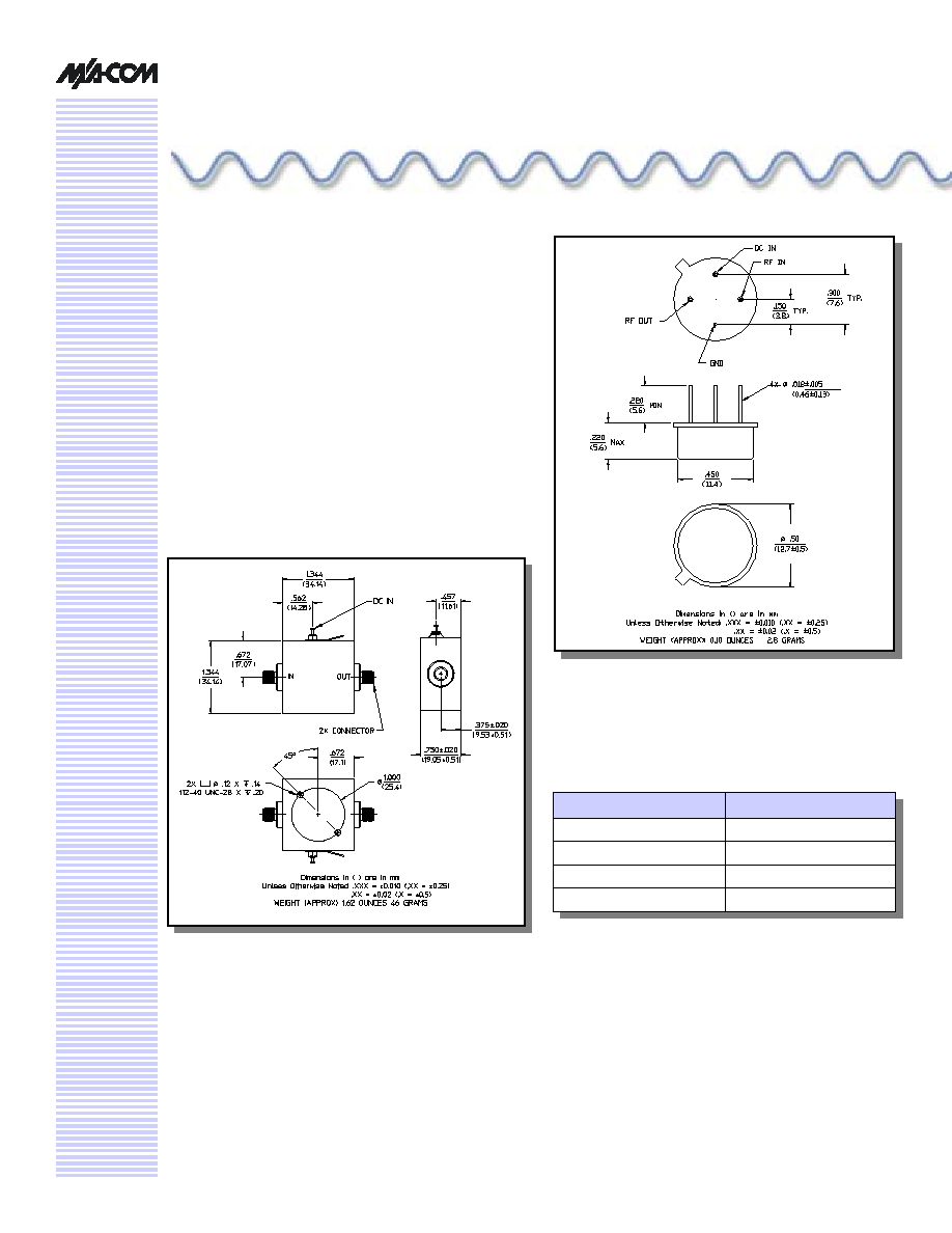
Ordering Information
Part Number
Package
AM-145 PIN
4
TO-8-1
AMC-145 SMA
Connectorized
4. Mounting kit part number AU00071 required for PCB
applications.
16
17
18
19
20
10
20
50
100
300
500
700
900
1100
1300
Frequency (MHz)
Ou
tp
u
t
P
o
we
r (d
Bm)
1.0
1.5
2.0
2.5
3.0
10
20
50
100
300
500
700
900
1100 1300
Frequency (MHz)
VSWR
RF IN
RF OUT
2
3
4
5
6
10
20
50
100
300
500
700
900
1100
1300
Frequency (MHz)
N
o
ise Figur
e (dB
)
+85∞C
+25∞C
30
40
50
60
10
20
50
100
300
500
700
900
1100
1300
Frequency (MHz)
In
te
rc
e
p
t (d
B
m
)
IP2 (f1+f2)
IP2 (f1-f2)
IP3
10
11
12
13
10
20
50
100
300
500
700
900
1100 1300
Frequency (MHz)
Gain
(d
B)
+85∞C
+25∞C
-55∞C