C-25
Features
n
4 dB Typical Midband Noise Figure
n
+38 dBm Typical Midband Third Order Intercept
n
+24 dBm Typical Midband 1 dB Compression
Description
M/A-COM's AM-146 is a coupler feedback amplifier with
high intercept and compression points. The use of coupler
feedback minimizes current in a high intercept amplifier.
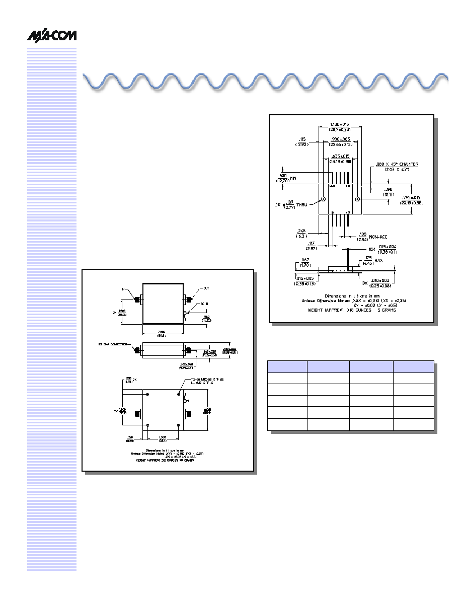
This amplifier is packaged in a flatpack with flanges. Due
to the metal flatpack the thermal rise minimized. The
ground plane on the PC board should be configured to
remove heat from under the package. AM-146 is ideally
suited for use where a high intercept, high reliability
amplifier is required.
High Performance Amplifier,
21 dB Gain, 10 - 500 MHz
AM
-
/AMC
-
146
FP-9
Pin Configuration
Pin No.
Function
Pin No.
Function
1
RF OUT
6
RF IN
2
GND
7
GND
3
GND
8
GND
4
GND
9
GND
5
VDC
10
VDC
V3.00

High Performance Amplifier, 21 dB Gain, 10 - 500 MHz
AM-/AMC-146
Specifications subject to change without notice.
n
North America: Tel. (800) 366-2266
n
Asia/Pacific: Tel.+81-44-844-8296, Fax +81-44-844-8298
n
Europe: Tel. +44 (1344) 869 595, Fax+44 (1344) 300 020
Visit www.macom.com for additional data sheets and product information.
V3.00
2
Electrical Specifications
1,2
T
A
= -55∞C to +85∞C Case Temperature
Parameter
Test Conditions
Frequency
Units
Min.
Typ.
Max.
Gain
@ +25∞C
50 MHz
dB
20.3
21.0
21.7
Frequency Response
--
10-500 MHz
dB
--
--
±1.0
Gain Variation with
Temperature
--
10-500 MHz
dB
--
--
+0.8,-1.2
1 dB Compression
Output Power
10-500 MHz
dBm
+20.0
--
--
Noise Figure
--
10-500 MHz
10-300 MHz
dB
dB
--
--
--
--
7.0
5.5
Reverse Transmission
--
10-500 MHz
dB
--
-35
-30
VSWR
--
10-500 MHz
Ratio
--
--
2:1
Output IP
2
Two-tone inputs up to +10 dBm
10-500 MHz
dBm
+40
--
--
Output IP
3
Two-tone inputs up to +10 dBm
10-500 MHz
dBm
+30
--
--
Vbias
--
--
VDC
+14.5
+15.0
+15.5
Ibias
Vbias = +15.0 VDC
--
mA
--
130
140
Power Dissipation
@ +15V Bias
--
W
--
2
--
Absolute Maximum Ratings
3
Parameter
Absolute Maximum
Max. Input Power
+10 dBm
V
bias
+15.75 V
Operating Temperature
-55∞C to +85∞C
Storage Temperature
-65∞C to +125∞C
3. Operation of this device above any one of these
parameters may cause permanent damage.
1. All specifications apply when operated at +15 VDC, with 50 ohms source and load impedance.
2. Heat Sinking: Operation at case temperature above 95∞C is not recommended. Heat sinking adequate to dissipate 2 W must be
provided in use.
S-Parameter Data
S11
S21
S12
S22
MAG
ANG
MAG
ANG
MAG
ANG
MAG
ANG
10
0.13
-118.5
11.44
16.8
0.02
7.1
0.14
164.6
20
0.12
-144.0
11.63
-1.0
0.02
-4.0
0.16
168.2
200
0.16
121.4
11.24
-120.3
0.02
-113.3
0.05
160.6
500
0.23
13.1
10.84
31.1
0.01
75.6
0.23
174.8
Frequency (MHz)
50
0.13
-175.5
11.56
-27.1
0.02
-25.3
0.15
155.9
75
0.14
169.0
11.49
-44.3
0.02
-41.3
0.13
143.8
100
0.15
163.8
11.45
-59.9
0.02
-55.7
0.08
132.5
300
0.18
86.3
11.34
176.4
0.02
-170.1
0.07
167.7
400
0.20
55.2
11.33
110.4
0.02
133.3
0.12
159.2
High Performance Amplifier, 21 dB Gain, 10 - 500 MHz
AM-/AMC-146
Specifications subject to change without notice.
n
North America: Tel. (800) 366-2266
n
Asia/Pacific: Tel.+81-44-844-8296, Fax +81-44-844-8298
n
Europe: Tel. +44 (1344) 869 595, Fax+44 (1344) 300 020
Visit www.macom.com for additional data sheets and product information.
V3.00
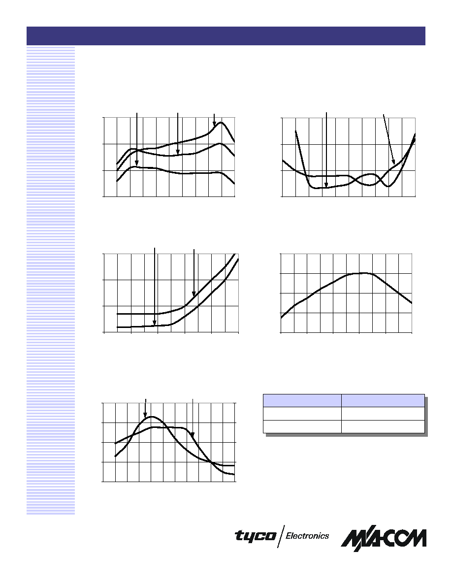
Typical Performance Curves
VSWR vs. Frequency
Gain vs. Frequency
Noise Figure
3
1 dB Compression
Intermodulation Intercept
Ordering Information
Part Number
Package
AM-146 PIN
Flatpack
AMC-146 SMA
Connectorized
18
20
22
24
26
3
5
10
20
50
100
200
300
400
500
600
Frequency (MHz)
Output Power (dBm)
1.0
1.5
2.0
2.5
3
5
10
20
50
100
200
300
400
500
600
Frequency (MHz)
VSWR
RF IN
RF OUT
3
4
5
6
3
5
10
20
50
100
200
300
400
500
600
Frequency (MHz)
Noise Figure (dB)
+25∞C
+85∞C
40
50
60
70
80
3
5
10
20
30
50
100 200 300 400 500 600
Frequency (MHz)
IP2 (dBm)
30
34
38
42
46
IP3 (dBm)
IP2
IP3
19.5
20.5
21.5
22.5
3
5
10
20
50
100
200
300
400
500
600
Frequency (MHz)
Gain (dB)
+85∞C
+25∞C
-55∞C