 | –≠–ª–µ–∫—Ç—Ä–æ–Ω–Ω—ã–π –∫–æ–º–ø–æ–Ω–µ–Ω—Ç: AM-147PIN | –°–∫–∞—á–∞—Ç—å:  PDF PDF  ZIP ZIP |
Features
n
2 dB Typical Midband Noise Figure
n
+20 dBm Typical Midband Output Power
n
+38 dBm Typical Midband Third Order Intercept
Description
M/A-COM's AM-147 is a coupler feedback amplifier with
high intercept and compression points. The use of coupler
feedback minimizes noise figure and current in a high
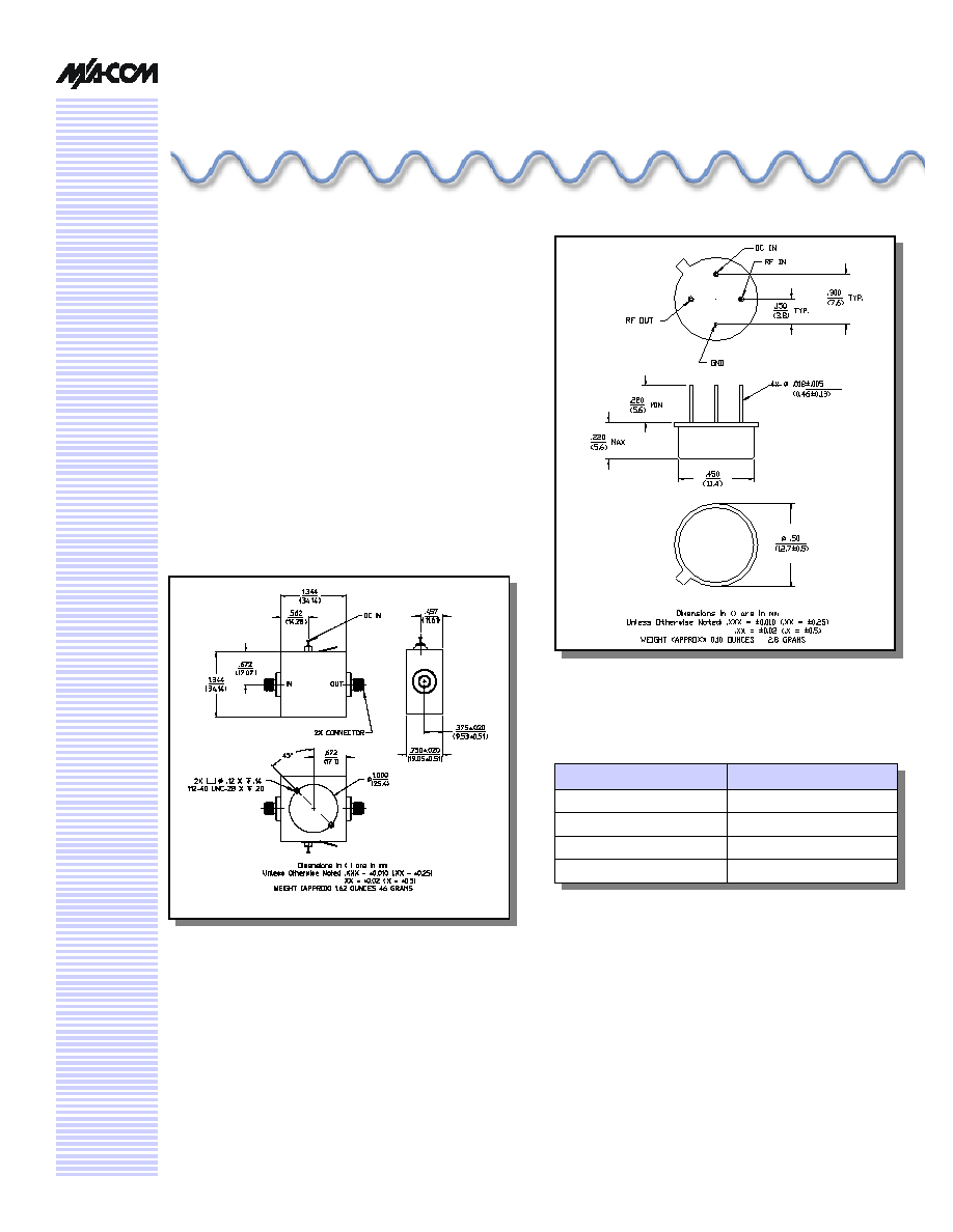
intercept amplifier. This amplifier is packaged in a TO-8
package. Due to the internal power dissipation the thermal
rise minimized. The ground plane on the PC board should
be configured to remove heat from under the package.
AM-147 is ideally suited for use where a high intercept,
high reliability amplifier is required.
High Performance Amplifier,
17 dB Gain, 5 - 500 MHz
AM
-
/AMC
-
147
TO-8-1
C-32
Absolute Maximum Ratings
1
1. Operation of this device above any one of these
parameters may cause permanent damage.
Parameter
Absolute Maximum
Max. Input Power
+10 dBm
V
bias
+15.75 V
Operating Temperature
-55∞C to +85∞C
Storage Temperature
-65∞C to +125∞C
V 3.00
High Performance Amplifier, 17 dB Gain, 5 - 500 MHz
AM-/AMC-147
Specifications subject to change without notice.
n
North America: Tel. (800) 366-2266
n
Asia/Pacific: Tel.+81-44-844-8296, Fax +81-44-844-8298
n
Europe: Tel. +44 (1344) 869 595, Fax+44 (1344) 300 020
Visit www.macom.com for additional data sheets and product information.
V 3.00
2
Electrical Specifications
2,3
T
A
= -55∞C to +85∞C Case Temperature
Parameter
Test Conditions
Frequency
Units
Min.
Typ.
Max.
Gain
@ +25∞C
50 MHz
dB
16.4
17.0
17.6
Frequency Response
--
5 - 500 MHz
dB
--
--
± 1.0
Gain Variation with
Temperature
--
5 - 500 MHz
dB
--
--
-1.2,+0.5
1 dB Compression
Output Power
5 - 500 MHz
dBm
+19
--
--
Noise Figure
--
5 - 500 MHz
5 - 300 MHz
dB
dB
--
--
--
--
4.5
3.5
Reverse Transmission
--
5 - 500 MHz
dB
--
-20
-16
VSWR
--
5 - 500 MHz
Ratio
--
--
2.0:1
Output IP
2
Two-tone inputs up to +5 dBm
5 - 500 MHz
dBm
+38
--
--
Output IP
3
Two-tone inputs up to +5 dBm
5 - 500 MHz
dBm
+28
--
--
Vbias
--
--
VDC
+14.5
+15.0
+15.5
Ibias
Vbias = +15.0 VDC
--
mA
--
50
60
Power Dissipation
@ +15V Bias
--
mW
--
750
--
2. All specifications apply when operated at +15 VDC, with 50 ohms source and load impedance.
3. Heat Sinking: Operation at case temperature above 95∞C is not recommended. Heat sinking adequate to dissipate 850 mW
must be provided in use.
S11
S21
S12
S22
MAG
ANG
MAG
ANG
MAG
ANG
MAG
ANG
5
0.19
-68.2
6.75
-153.1
0.09
-152.0
0.20
-21.0
10
0.11
-78.1
7.05
-167.3
0.09
-168.0
0.12
-22.9
200
0.11
-122.1
7.17
136.3
0.11
130.3
0.13
3.8
500
0.17
164.6
7.24
67.9
0.12
66.5
0.19
-38.9
Frequency (MHz)
20
0.07
-83.8
7.17
-176.4
0.10
-177.7
0.10
-13.5
50
0.06
-95.0
7.15
171.4
0.10
170.1
0.09
-1.9
100
0.07
-100.1
7.14
159.2
0.10
156.7
0.10
2.6
300
0.14
-141.7
7.08
114.7
0.11
108.4
0.14
-5.5
400
0.15
-166.3
7.16
91.0
0.11
86.6
0.17
-19.9
S-Parameter Data
High Performance Amplifier, 17 dB Gain, 5 - 500 MHz
AM-/AMC-147
Specifications subject to change without notice.
n
North America: Tel. (800) 366-2266
n
Asia/Pacific: Tel.+81-44-844-8296, Fax +81-44-844-8298
n
Europe: Tel. +44 (1344) 869 595, Fax+44 (1344) 300 020
Visit www.macom.com for additional data sheets and product information.
V 3.00
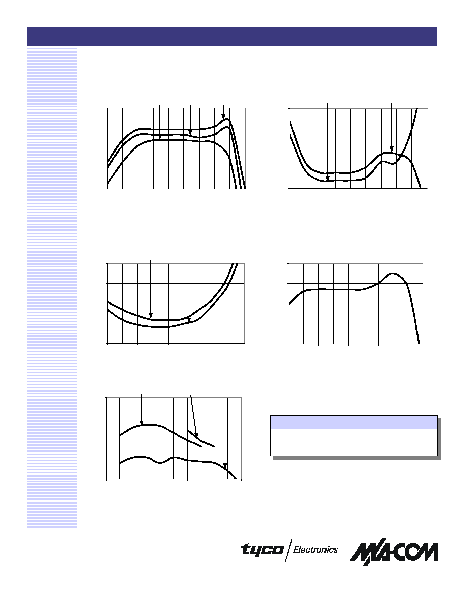
Typical Performance Curves
Noise Figure
3
Ordering Information
4. Mounting kit part number AU00071 required for PCB
applications.
Part Number
Package
AM-147 PIN
4
TO-8-1
AMC-147 SMA
Connectorized
1 dB Compression
Intermodulation Intercept
Gain vs. Frequency
VSWR vs. Frequency
18
19
20
21
22
3
5
10
20
50
100
300
500
700
900
Frequency (MHz)
Output Power (dBm)
15
16
17
18
3
5
10
20
50
100
300
500
700
900
Frequency (MHz)
Gain (dB)
85∞C
25∞C
-55∞C
1.0
1.5
2.0
2.5
3
5
10
20
50
100
300
500
700
900
Frequency (MHz)
VSWR
RF IN
RF OUT
1
2
3
4
5
3
5
10
20
50
100
300
500
700
900
Frequency (MHz)
Noise Figure (dB)
+85∞C
+25∞C
30
40
50
60
3
5
10
20
50
100
300
400
500
700
900
Frequency (MHz)
Intercept (dBm)
IP2 (f1+f2)
IP2 (f1-f2)
IP3