Features
n
1.9 dB Typical Midband Noise Figure
n
+7.5 dBm Typical Midband Output Power
n
+19 dBm Typical Midband Third Order Intercept
Description
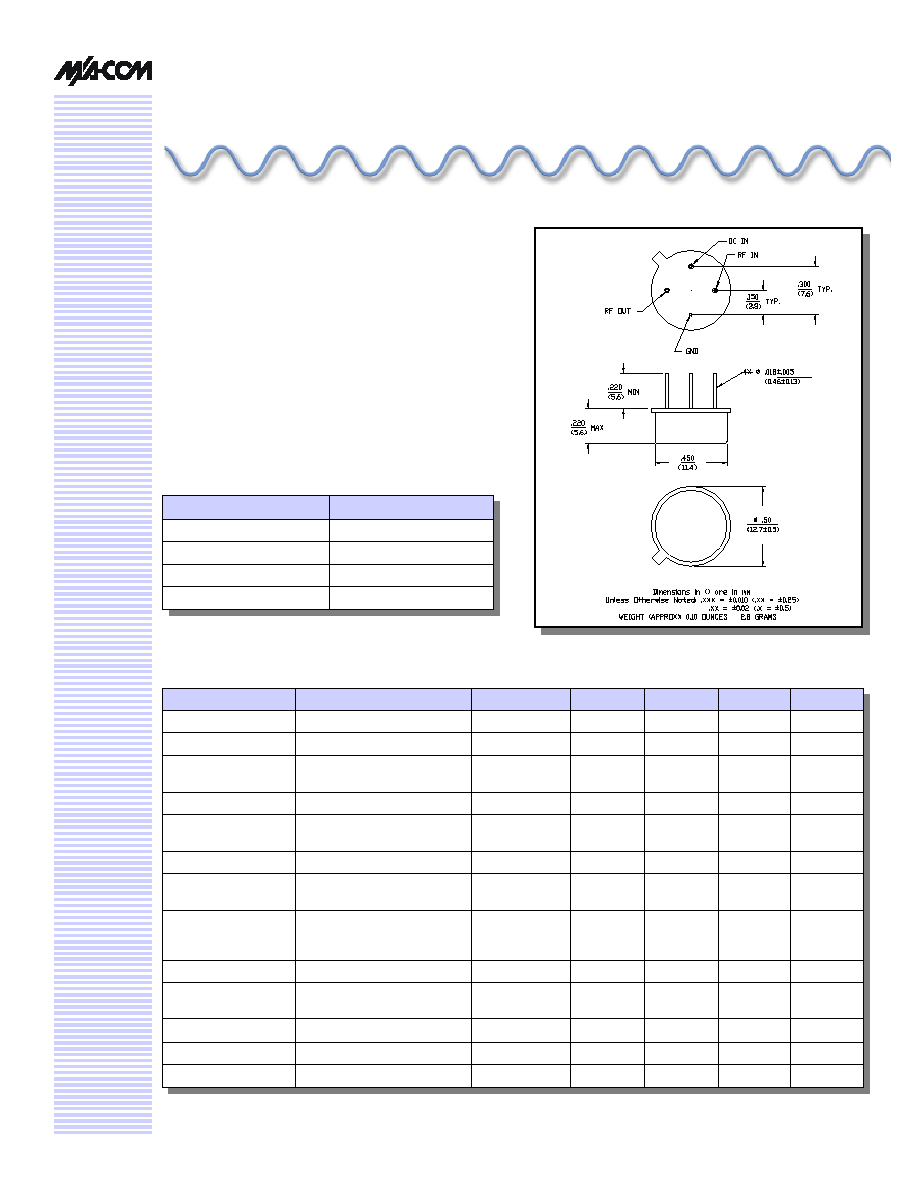
M/A-COM's AM-153 is a coupler feedback amplifier with
low noise figure. The use of coupler feedback minimizes
noise figure and current in a high intercept amplifier. This
amplifier is packaged in a TO-8 package. This unique
design features low noise figure over a wide bandwidth.
AM-153 is ideally suited for use where a low noise,
wideband, high reliability amplifier is required.
Low Noise Amplifier, 12 dB Gain,
300 - 1800 MHz
AM
-
153
TO-8-1
Absolute Maximum Ratings
1
1. Operation of this device above any one of these
parameters may cause permanent damage.
Parameter
Absolute Maximum
Max. Input Power
+10 dBm
V
bias
+15.75 V
Operating Temperature
-55∞C to +85∞C
Storage Temperature
-65∞C to +125∞C
Electrical Specifications
2
T
A
= -55∞C to +85∞C Case Temperature
Parameter
Test Conditions
Frequency
Units
Min.
Typ.
Max.
Gain
@ +25∞C
600 MHz
dB
11.9
12.4
12.9
Frequency Response
--
300-1800 MHz
dB
--
--
±1.2
Gain Variation with
Temperature
--
300-1800 MHz
dB
--
--
+0.5/-0.7
1 dB Compression
Output Power
300-1800 MHz
dBm
+6
--
--
Noise Figure
--
300-1500 MHz
1500-1800 MHz
dB
dB
--
--
--
--
3.0
3.5
Reverse Transmission
--
300-1800 MHz
dB
--
-14
-12
VSWR Input
--
300-1500 MHz
1500-1800 MHz
Ratio
Ratio
--
--
--
--
2.5:1
3.3:1
VSWR Output
--
300-400 MHz
400-1500 MHz
1500-1800 MHz
Ratio
Ratio
Ratio
--
--
--
--
--
--
3.5:1
3.0:1
2.5:1
Output IP
2
Two-tone inputs up to ≠5 dBm
300-1800 MHz
dBm
+22
--
--
Output IP
3
Two-tone inputs up to ≠5 dBm
300-1000 MHz
1000-1800 MHz
dBm
dBm
+17
+15
--
--
--
--
Vbias
--
--
VDC
+14.5
+15.0
+15.5
Ibias
Vbias = +15.0 VDC
--
mA
--
13
15
Power Dissipation
@ +15V Bias
--
mW
--
200
--
2. All specifications apply when operated at +15 VDC, with 50 ohms source and load impedance.
V 3.00

Low Noise Amplifier, 12 dB Gain, 300 - 1800 MHz
AM-153
Specifications subject to change without notice.
n
North America: Tel. (800) 366-2266
n
Asia/Pacific: Tel.+81-44-844-8296, Fax +81-44-844-8298
n
Europe: Tel. +44 (1344) 869 595, Fax+44 (1344) 300 020
Visit www.macom.com for additional data sheets and product information.
V 3.00
Typical Performance Curves
Noise Figure
2
Ordering Information
3. Mounting kit part number AU00071 required for PCB
applications.
Part Number
Package
AM-153 PIN
3
TO-8-1
1 dB Compression
Intermodulation Intercept
Gain vs. Frequency
VSWR vs. Frequency
5
6
7
8
9
200
300
500
700
1000
1500
1800
2000
Frequency (MHz)
Output Power (dBm)
10
11
12
13
200
300
500
700
1000
1500
1800
2000
Frequency (MHz)
Gain (dB)
85∞C
25∞C
-55∞C
1.0
1.5
2.0
2.5
3.0
200
300
500
700
1000
1500
1800
2000
Frequency (MHz)
VSWR
RF IN
RF OUT
1
2
3
200
300
500
700
1000
1500
1800
2000
Frequency (MHz)
Noise Figure (dB)
+85∞C
+25∞C
15
20
25
30
200
300
500
700
1000
1500
1800
2000
Frequency (MHz)
Intercept (dBm)
IP2 (f1+f2)
IP3