 | –≠–ª–µ–∫—Ç—Ä–æ–Ω–Ω—ã–π –∫–æ–º–ø–æ–Ω–µ–Ω—Ç: AM42-0046 | –°–∫–∞—á–∞—Ç—å:  PDF PDF  ZIP ZIP |

Features
∑ High Linear Gain: 30 dB Typical
∑ High Saturated Output Power: +36 dBm Typ.
∑ High Power Added Efficiency: 25% Typical
∑ 50 Input / Output Broadband Matched
∑ Integrated Output Power Detector
Description
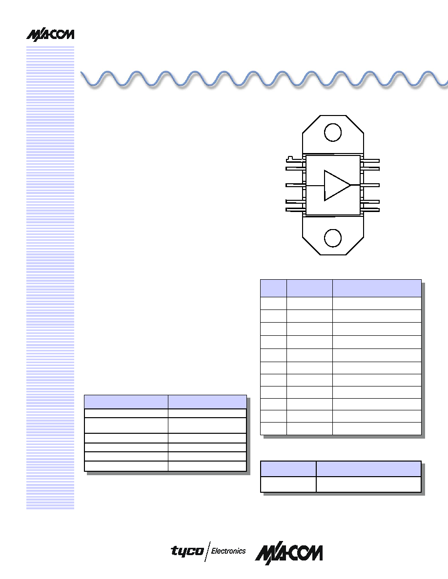
M/A-COM's AM42-0046 is a three stage MMIC
power amplifier in a bolt down ceramic package,
allowing easy assembly. The AM42-0046 employs
a fully matched chip with internally decoupled gate
and drain bias networks. The AM42-0046 is
designed to operate from a constant current drain
supply or a constant voltage gate supply. By
varying the bias conditions, the saturated output
power performance of this device may be tailored
for various applications.
The AM42-0046 is ideally suited for use as an
output stage or a driver amplifier in VSAT systems.
The AM42-0046 includes internal supply line
bypassing in the
package, minimizing the number of
external components required.
M/A-COM's AM42-0046 is fabricated using a mature
0.5 micron MBE based GaAs MESFET process. The
process features full passivation for increased
performance and reliability. This product is 100% RF
tested to ensure compliance to performance
specifications.
AM42-0046
Functional Schematic
4 Watt Extended C-Band VSAT Power Amplifier
5.9 - 7.1 GHz
V1P
AM42-0046
Ordering Information
Part Number
Package
AM42-0046
CR15 Ceramic Bolt Down Package
Parameter
Absolute Maximum
Input Power
+15 dBm
Operating Voltages
V
DD
= +10 volts;
V
GG
= -3 volts
Ids 2300
mA
Channel Temperature
+150 ∞C
Operating Temperature
-40 ∞C to +80 ∞C
Storage Temperature
-65 ∞C to +150 ∞C
Absolute Maximum Ratings
1,2
Pin Configuration
PIN
No.
PIN Name
Description
1
V
DD1,2
1st and 2nd Drain Supply
2
GND
DC and RF Ground
3
RF
IN
RF Input
4
V
GG
Gate Supply
5
GND
DC and RF Ground
6
GND
DC and RF Ground
7
V
DET
Output Power Detector
8
RF
OUT
RF Output
9
V
DD3
3rd Stage Drain Supply
10
V
DD1,2
1st and 2nd Drain Supply
Flange
GND
DC and RF Ground
1. Exceeding any one or a combination of these limits may
cause permanent damage.
2. Adequate heat sinking and grounding required on flange
base.
M/A-COM Inc. and its affiliates reserve the right to make changes to the product(s)
or information contained herein without notice.
Visit www.macom.com for additional data sheets and product information.
North America: Tel. (800) 366-2266
Asia/Pacific: Tel. +81-44-844-8296, Fax +81-44-844-8298
Europe: Tel. +44 (1908) 574 200, Fax +44 (1908) 574 300
1
V
DD1,2
RF
OUT
V
DET
V
GG
RF
IN
GND
V
DD1,2
GND
GND
V
DD3
V
DD1,2
RF
OUT
V
DET
V
GG
RF
IN
GND
V
DD1,2
GND
GND
V
DD3

4 Watt Extended C-Band VSAT Power Amplifier, 5.9 - 7.1 GHz
AM42-0046
V1P
M/A-COM Inc. and its affiliates reserve the right to make changes to the product(s)
or information contained herein without notice.
Visit www.macom.com for additional data sheets and product information.
North America: Tel. (800) 366-2266
Asia/Pacific: Tel. +81-44-844-8296, Fax +81-44-844-8298
Europe: Tel. +44 (1908) 574 200, Fax +44 (1908) 574 300
2
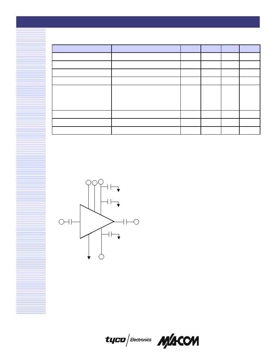
Application Schematic
3
Electrical Specifications:
V
DD1,2,3
= +8 Vdc; V
GG
= -5 Vdc; T
A
= 25∞C, Z
0
= 50
Parameter
Test Conditions
Units
Min.
Typ.
Max.
Linear Gain
Pin = -4 dBm
dB
27
30
Input VSWR
Pin = -4 dBm
2.5:1
3.0:1
Output VSWR
Pin = -4 dBm
2.5:1
Output Power
Pin = +8 dBm, Ids = 1900 mA Typ.
dBm
35
36.0
Output Power vs. Frequency
Pin = +3 dBm, Ids = 1900 mA Typ.
(5.9 to 6.4 GHz)
Pin = +8 dBm, Ids = 1900 mA Typ.
(6.4 to 7.1 GHz)
dB
dB
±0.3
±0.3
±1.25
±1.25
Drain Bias Current
Pin = +8 dBm
mA
1900
2200
Gate Bias Current
Pin = +8 dBm, Ids = 1900 mA Typ.
mA
10
25
Detector Voltage
Pin = +8 dBm, Ids = 1900 mA Typ.
V
2.0
4.0
3. External DC blocking capacitors required on the RF ports.
Operating the AM42-0046
The AM42-0046 is static sensitive. Please handle with
care. To operate the device, follow these steps.
1. Apply -5.0 Volts to V
GG
.
2. Ramp V
DD
to +8 V.
3. Apply RF.
4. Power down sequence in reverse. Turn gate
voltage off last.
Handling Procedures
Please observe the following precautions to
avoid damage to the AM42-0046:
Static Sensitivity
Gallium arsenide integrated circuits are ESD
sensitive and can be damaged by static
electricity. Use proper ESD precautions when
handling these devices.
RF Out
8
RF In
3
1.0 µF
V
GG
4
GND
2,5,6
100 pF
100 pF
V
DD 1,2
1 or 10
1.0 µF
0.01 µF
AM42-0046
V
DET
7
V
DD3
9

4 Watt Extended C-Band VSAT Power Amplifier, 5.9 - 7.1 GHz
AM42-0046
V1P
M/A-COM Inc. and its affiliates reserve the right to make changes to the product(s)
or information contained herein without notice.
Visit www.macom.com for additional data sheets and product information.
North America: Tel. (800) 366-2266
Asia/Pacific: Tel. +81-44-844-8296, Fax +81-44-844-8298
Europe: Tel. +44 (1908) 574 200, Fax +44 (1908) 574 300
3
CR-15
CERAMIC
BASE PLATE
4X .06 X 45∞
CHAMFER
6
5
4
3
2
1
7
8
9
10
.010 SQ.
ORIENTATION TAB
2X o .096 THRU
o.004 M
A B C
.090
MAX
.33
.005
± .002
.030
.318
± .010
.328
± .010
.050 MIN.
10X
.530
.70
.159
.010
± .003
10X
.040
.100
4X
.115
± .010
.050
4X
.085
- C -
- B -
- A -
15
20
25
30
35
40
5.9
6.2
6.5
6.8
7.1
Frequency (GHz)
0
10
20
30
40
50
5.9
6.2
6.5
6.8
7.1
Frequency (GHz)
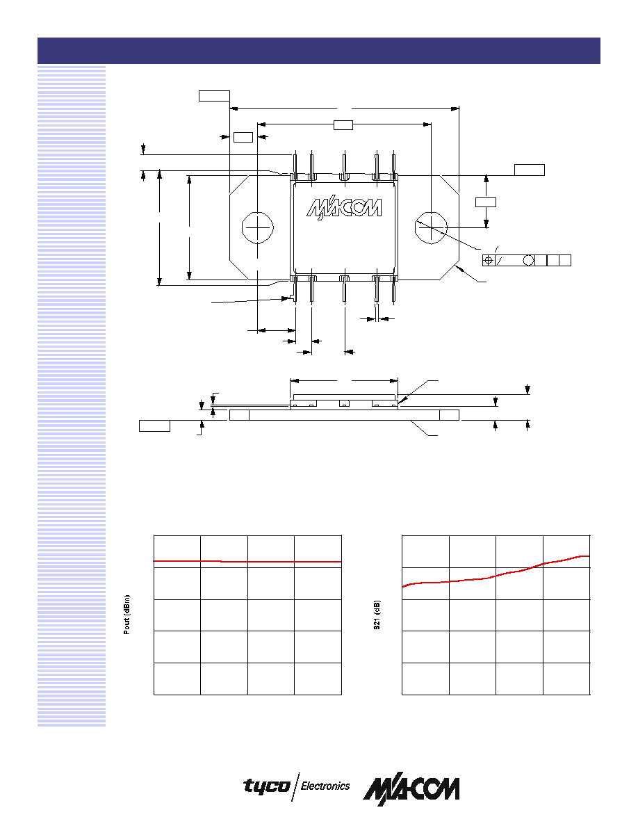
Typical Performance Curves
P
OUT
vs. Frequency
S21 vs. Frequency


