
Features
n
Ideal for Base Station Applications
n
High Gain
n
Low Noise Figure
n
High Input IP
3
n
Single +5 V Supply Voltage
Description
M/A-COM's AM50-0011 is a high dynamic range, GaAs
MMIC, low noise amplifier in a low-cost SOT-26 package.
It employs external matching to obtain optimum noise
figure and intercept performance. The AM50-0011 may be
operated with supply voltages of +5 V.
The AM50-0011 is ideally suited for use where low noise
figure, high gain, and high dynamic range are required.
Typical applications included receiver front ends in AMPS,
GSM and ETACS base stations. It may also be used as an
IF amplifier in certain other communication systems.
M/A-COM fabricates the AM50-0011 using a low-cost 0.5-
micron gate E-D SAGFET GaAs process that features full
passivation for reliability and performance. M/A-COM
fully tests all assembled GaAs IC's for RF and DC
performance against guaranteed specifications using
automated RF IC handling and test equipment before
shipping to customers.
High Dynamic Range LNA
800 - 1000 MHz
AM50
-
0011
PIN No.
PIN
Description
1
VBC
Bias Control Voltage
2
GND
Ground
3
RF IN
RF Input
4
GND
Ground
5
GND
Ground
6
RF OUT RF Output
Functional Schematic
Pin Configuration
IN
GND
OUT
VDD
VBC
GND
C1
L2
C3
L1
C2
GND
Part
Value
L1
7.5 nH
L2
68 nH
C1
33 pF
C2
100 pF
C3
100 pF
Parameter
Absolute Maximum
Supply Voltage
6 volts
RF Input Power
8 dBm
Operating Temperature
-40� to +85 �C
Storage Temperature
-65� to +150 �C
Absolute Maximum Ratings
1
1. Exceeding any one or combination of these limits may
cause permanent damage.
2. Minimum MTTF is 1x10
6
85
�
C, at +5 V and 75 mA
V 2.00
High Dynamic Range LNA, 800 - 1000 MHz
AM50-0011
Specifications subject to change without notice.
n
North America: Tel. (800) 366-2266
n
Asia/Pacific: Tel.+81-44-844-8296, Fax +81-44-844-8298
n
Europe: Tel. +44 (1344) 869 595, Fax+44 (1344) 300 020
Visit www.macom.com for additional data sheets and product information.
V 2.00
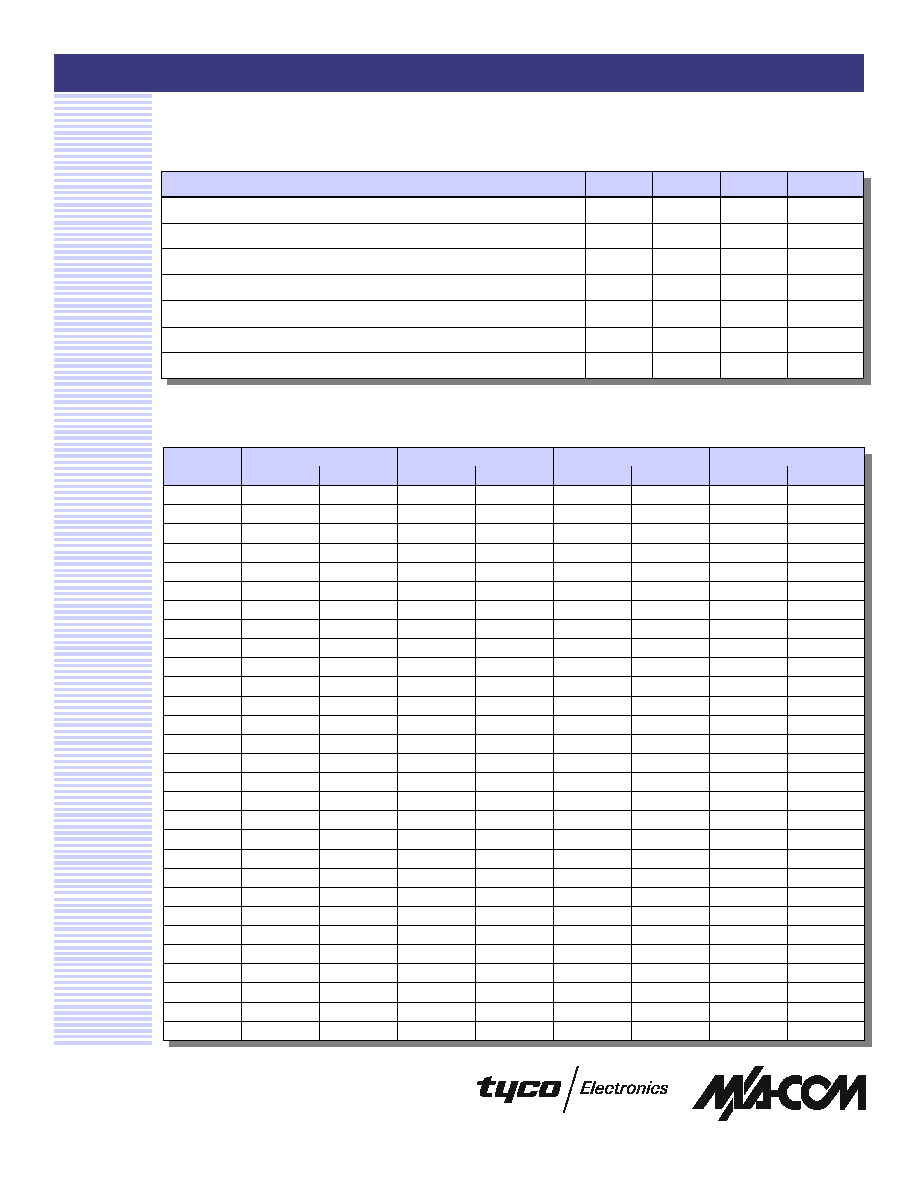
Electrical Specifications: T
A
= 25 �C, Z
0
= 50
, F = 900 MHz, P
IN
= -25 dBm,
V
BC
= 5 V, Supply Voltage = 5 V
1
Parameter
Units
Min.
Typ.
Max.
Gain
dB
15
16
17
Noise Figure
dB
0.8
1.3
Output P
1dB
dBm
15.5
Supply Current
mA
52
75
Input IP
3
dBm
12
14.4
Input V
SWR
1.8:1
Output V
SWR
1.9:1
2
1. All measurements are taken into a 50-ohm system unless otherwise specified.
Frequency
S21
S12
S22
MHz
Mag
Ang
Mag
Ang
Mag
Ang
Mag
Ang
200
0.48
-49.66
9.34
154.18
0.03
27.77
0.22
176.29
300
0.51
--66.15
8.88
142.56
0.04
22.36
0.25
168.84
400
0.53
-79.22
8.21
134.07
0.04
29.75
0.23
165.03
500
0.54
-91.86
7.60
125.78
0.05
36.41
0.26
155.77
S11
600
0.57
-101.06
7.12
117.55
0.05
33.59
0.26
152.78
700
0.58
-110.79
6.46
110.04
0.06
33.73
0.27
147.26
800
0.59
-117.54
6.05
104.16
0.06
33.13
0.27
141.77
900
0.60
-124.29
5.55
97.31
0.06
34.47
0.28
135.23
1000
0.61
-129.68
5.18
92.23
0.07
33.42
0.28
130.14
1100
0.63
-135.05
4.83
86.25
0.08
31.44
0.29
124.27
1200
0.64
-139.81
4.49
81.33
0.08
33.56
0.30
117.78
1300
0.64
-144.08
4.19
76.49
0.08
32.18
0.31
110.61
1400
0.66
-147.34
3.94
71.84
0.09
29.66
0.32
105.59
1500
0.66
-151.48
3.69
67.45
0.09
28.63
0.34
99.61
1600
0.67
-154.72
3.49
62.89
0.10
28.38
0.36
96.38
1700
0.68
-158.72
3.23
59.27
0.10
27.84
0.39
92.40
1800
0.68
-162.04
3.04
55.70
0.10
26.22
0.40
89.88
1900
0.69
-164.46
2.88
52.15
0.10
25.25
0.41
88.46
2000
0.69
-166.68
2.74
48.73
0.11
23.15
0.42
85.35
2100
0.69
-169.52
2.59
45.76
0.11
23.26
0.43
83.28
2200
0.69
-171.95
2.49
41.82
0.11
21.07
0.44
78.45
2300
0.69
-173.86
2.37
38.64
0.12
19.72
0.44
76.69
2400
0.70
-175.94
2.25
35.32
0.12
18.62
0.44
72.60
2500
0.70
-177.82
2.17
31.63
0.12
15.49
0.43
67.17
2600
0.71
-179.80
2.06
27.98
0.12
14.81
0.45
62.63
2700
0.72
178.28
1.96
24.6
0.12
11.42
0.45
56.21
2800
0.72
176.15
1.87
21.63
0.13
10.29
0.47
51.44
2900
0.72
174.28
1.77
18.68
0.13
9.49
0.49
48.17
3000
0.73
172.15
1.69
15.50
0.13
7.26
0.52
43.42
Typical S-Parameters at 5.0 Volts
High Dynamic Range LNA, 800 - 1000 MHz
AM50-0011
Specifications subject to change without notice.
n
North America: Tel. (800) 366-2266
n
Asia/Pacific: Tel.+81-44-844-8296, Fax +81-44-844-8298
n
Europe: Tel. +44 (1344) 869 595, Fax+44 (1344) 300 020
Visit www.macom.com for additional data sheets and product information.
V 2.00
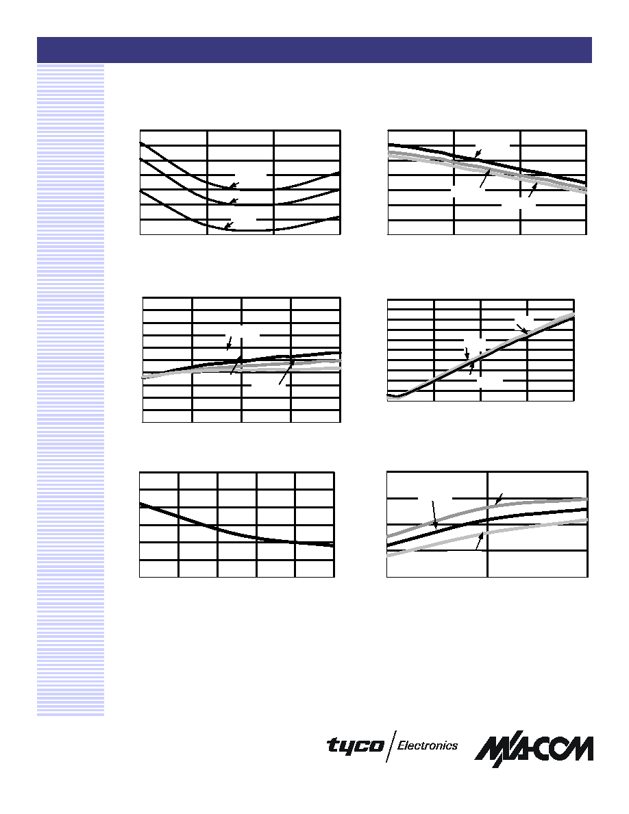
0.5
0.7
0.9
1.1
1.3
1.5
1.7
1.9
700
800
900
1000
FREQUENCY (MHz)
NF (dB)
85C
25C
-40C
Typical Performance Curves at V
DD
= 5 Volts
Typical Current
40
45
50
55
60
65
70
-40
-15
10
35
60
85
TEMPERATURE (�C)
Current (mA)
Typical Input IP
3
10
12
14
16
18
800
900
1000
FREQUENCY (MHz)
IP
3
(dBm)
25�C
85�C
-45�C
1.0
1.2
1.4
1.6
1.8
2.0
2.2
2.4
2.6
2.8
3.0
700
800
900
1000
1100
FREQUENCY (MHz)
VSWR
Output V
SWR
-45�C
25�C
85�C
12
13
14
15
16
17
18
19
700
800
900
1000
FREQUENCY (MHz)
Gain (dB)
Typical Gain
-45�C
25�C
85�C
Typical Noise Figure
3
1.0
1.2
1.4
1.6
1.8
2.0
2.2
2.4
2.6
2.8
3.0
700
800
900
1000
1100
FREQUENCY (MHz)
VSWR
25C
-45C
85C
Input V
SWR
High Dynamic Range LNA, 800 - 1000 MHz
AM50-0011
Specifications subject to change without notice.
n
North America: Tel. (800) 366-2266
n
Asia/Pacific: Tel.+81-44-844-8296, Fax +81-44-844-8298
n
Europe: Tel. +44 (1344) 869 595, Fax+44 (1344) 300 020
Visit www.macom.com for additional data sheets and product information.
V 2.00
Ordering Information
1. If specific reel size is required, consult factory for part
number assignment.
Part Number
Package
AM50-0011TR
1000 Tape and Reel
1
AM50-0011TR 3000
3000 Tape and Reel
1
AM50-0011SMB
Sample Test Board
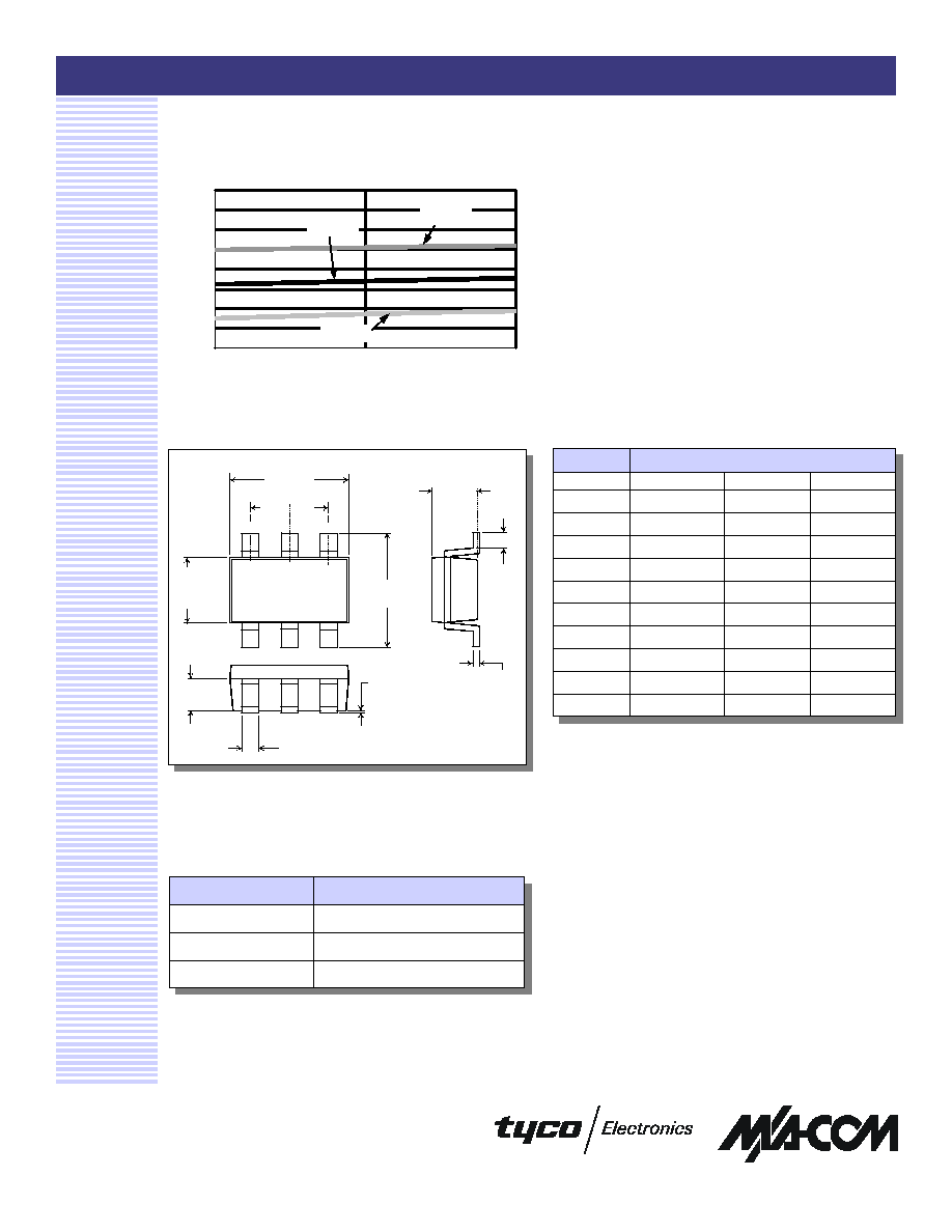
Typical P
1dB
12
13
14
15
16
17
18
19
20
800
900
1000
FREQUENCY (MHz)
P
1dB
(dBm)
25�C
-40�C
85�C
Typical Performance Curves at V
DD
= 5 Volts (Cont'd)
SOT-26
1
1. See EIAJ ED-7500A, SC-74 for additional dimensional and
tolerance information.
PIN 1
D
e e
H
E
E
A3
A1
b
c
L
A
Dim
Measurement (mm)
Min.
Nom.
Max.
A
0.90
1.10
1.30
A1
0
0.05
0.10
A3
0.62
0.79
1.89
b
0.35
0.40
0.50
c
0.10
0.15
0.25
D
2.70
2.90
3.10
e
0.95
E
1.50
1.60
1.80
HE
2.6
2.80
3.00
L
0.20
-
-
SOT-26
4