Features
n
Attenuation: 0.5 dB steps to 31.5 dB
n
6 Bit Digital Gain Control
n
CMOS Logic
n
Serial Logic Interface
n
Single Positive Voltage Supply
n
8 mm PBGA Package
n
JEDEC MO-151 Footprint
n
Single Package Solution for GSM,CDMA,PCS
Description
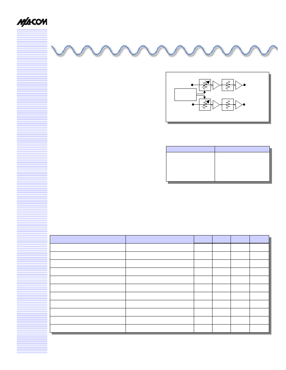
The M/A-COM AM55-0024 is a dual channel IF amplifier
and digital attenuator packaged in a multi-layer multi-chip
module (MCM). Gain control is via two separate serial
logic interfaces. The part utilizes Plastic Ball Grid Array
(PBGA) interconnect technology to achieve high circuit
density and superior performance. This device is ideal for
GSM/DCS/PCS digital base station applications where high
dynamic range gain control functionality is required.
Hi Dyn Range 2 Channel IF Amp with
Power Control, 100 - 400 MHz
AM55
-
0024
Functional Block Diagram
Parameter
Absolute Maximum
Input Power
2
+20 dBm
Operating Voltage
2
V
DD
= +6 V
Operating Temperature
-40�C to +85�C
Storage Temperature
-65�C to +150�C
Absolute Maximum Ratings
1
1. Exceeding any one or combination of these limits may
cause permanent damage.
2. Ambient Temperature (T
A
) = +25
�
C.
Logic
Interface
IF in B
IF in A
IF out B
IF out A
Electrical Specifications: T
A
= 25�C, Z
0
= 50
1
Parameter
Test Conditions
Units
Min.
Typ.
Max.
Gain
100 - 400 MHz
dB
19.5
21
22.5
Gain Control Range
100 - 400 MHz
dB
31.5
Minimum Gain Control Step Size
100 - 400 MHz
dB
0.5
Return Loss
100 - 400 MHz
dB
10
12
Output IP
3
100 - 400 MHz @ 5V
dBm
30
Supply Voltage
V
3/5
Supply Current
@ 3V / @ 5V
mA
300/400
Switching Speed (50% TTL to 90% RF)
nS
50
Isolation
dBc
50
60
P1 dB
dBm
15
17.5
Noise Figure
100 - 400 MHz
dB
4
1. All measurements in a 50 Ohm system.
V 2.00
Hi Dyn Range 2 Channel IF Amp w/Pwr Cntrl, 100 - 400 MHz
AM55-0024
Specifications subject to change without notice.
n
North America: Tel. (800) 366-2266
n
Asia/Pacific: Tel.+81-44-844-8296, Fax +81-44-844-8298
n
Europe: Tel. +44 (1344) 869 595, Fax+44 (1344) 300 020
Visit www.macom.com for additional data sheets and product information.
V 2.00
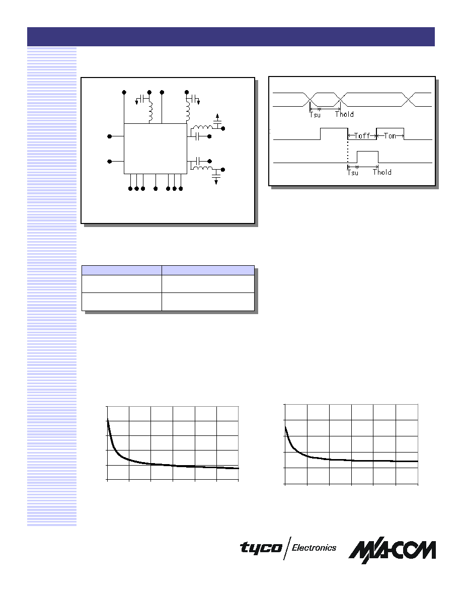
External Components
1, 2, 3
2
Typical Performance Curves
Output V
SWR
Input V
SWR
Component
Value
L
470 nH
C
10000 pF
1. All inductors are 470 nH
2. All Capacitors are 10000 pF
3. IF outputs must be supplied +3 Volts.
Clock Diagram
1, 2, 3, 4, 5
1. Max Clock Speed = 40 MHz
2. Ton = Toff
3. Tsu = >3ns
4. Thold = >7ns
5. Data clocked in on rising clock edge
Data
Clock
Each channel in the AM55-0024 is independently
controllable with a 3 wire serial interface: Clock, Data,
and Latch Enable. These lines can be shared based on
application requirements. The attenuator within the
device is controlled with a 6 bit word, enabling the
selection of 64 possible states. The highest gain state is
'000000', and the lowest is '111111'. The sequence for
shifting the data is as follows: Present data (MSB first),
strobe clock, repeat until 6 bits have been presented and
clocked, then strobe the latch enable line, which
implements the state change.
Serial Interface
1.0
1.5
2.0
2.5
3.0
3.5
0.045
0.105
0.165
0.225
0.285
0.345
0.405
Frequency (GHz)
VSWR (dB)
1.0
1.5
2.0
2.5
3.0
3.5
0.045
0.105
0.165
0.225
0.285
0.345
0.405
Frequency (GHz)
VSWR (dB)
AM55-0024
3V
A1
3V
A2
3V
B1
3V
B2
Clk A
Data A
Latch A
Digital V
DD
Clk B
Data B
Latch B
IF In A
IF In B
IF Out A
3V A3
IF Out B
3V B3
Latch
Hi Dyn Range 2 Channel IF Amp w/Pwr Cntrl, 100 - 400 MHz
AM55-0024
Specifications subject to change without notice.
n
North America: Tel. (800) 366-2266
n
Asia/Pacific: Tel.+81-44-844-8296, Fax +81-44-844-8298
n
Europe: Tel. +44 (1344) 869 595, Fax+44 (1344) 300 020
Visit www.macom.com for additional data sheets and product information.
V 2.00
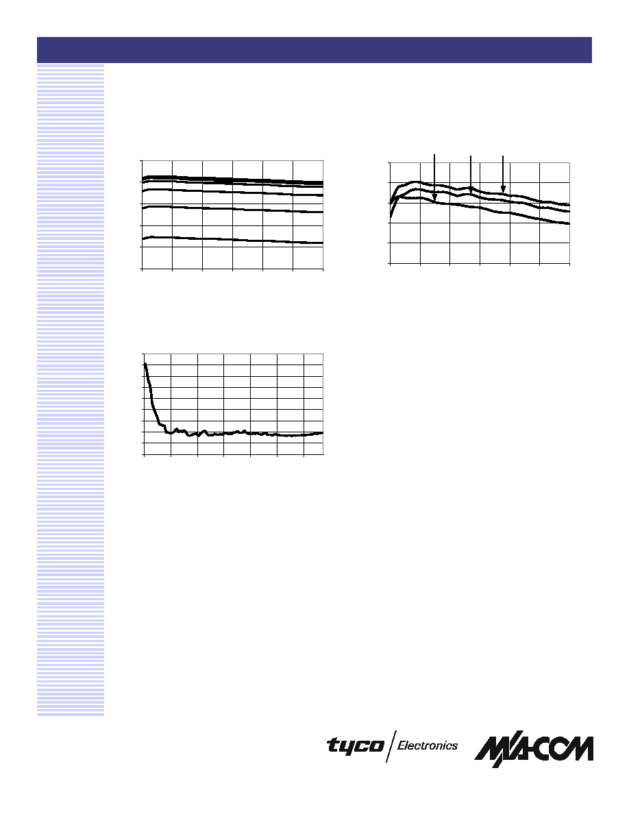
Typical Performance Curves (Cont'd)
Gain
Attenuation (6 individual bits)
3
Noise Figure
0
5
10
15
20
25
0.05
0.11
0.17
0.23
0.29
0.35
0.41
Frequency (GHz)
Attenuation (dB)
0
2
4
6
8
10
12
14
16
18
0.05
0.1175
0.185
0.2525
0.32
0.3875
0.455
Frequency (GHz)
Noise Figure (dB)
18
19
20
21
22
23
0.045
0.105
0.165
0.225
0.285
0.345
0.405
Frequency (GHz)
Gain (dB)
+85�C
+25�C
-40�C
Hi Dyn Range 2 Channel IF Amp w/Pwr Cntrl, 100 - 400 MHz
AM55-0024
Specifications subject to change without notice.
n
North America: Tel. (800) 366-2266
n
Asia/Pacific: Tel.+81-44-844-8296, Fax +81-44-844-8298
n
Europe: Tel. +44 (1344) 869 595, Fax+44 (1344) 300 020
Visit www.macom.com for additional data sheets and product information.
V 2.00
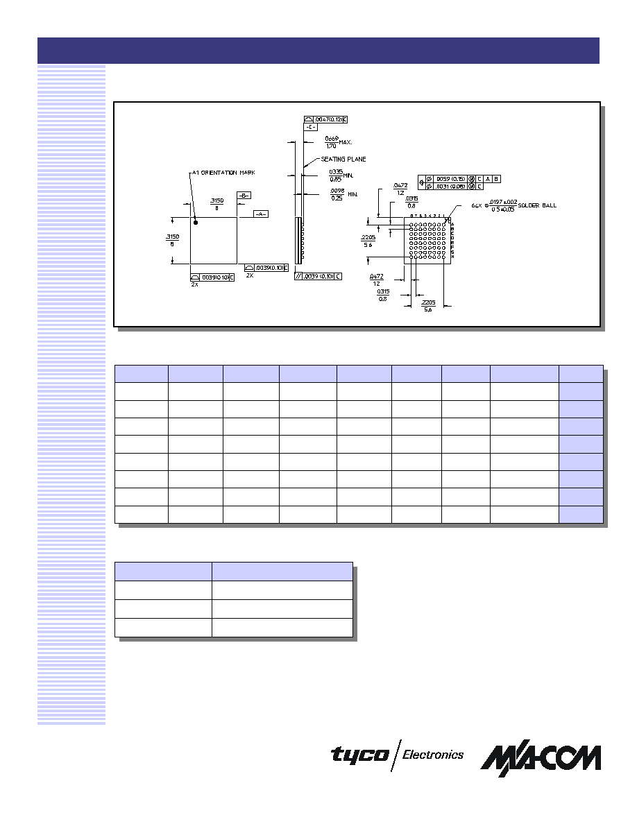
Ordering Information
1. If specific reel size is required, consult factory for part
number assignment.
Part Number
Package
AM55-0024
8-mm PBGA Package
AM55-0024TR
Forward Tape and Reel
1
AM55-0024RTR
Reverse Tape and Reel
4
8 mm PBGA
8
7
6
5
4
3
2
1
+5V_A1
DAT_A
CLK_A
+5V_A2
RF_OUT_A
A
B
RF_IN_A
C
LE_A
D
RF_IN_B
E
LE_B
F
CLK_B
G
DAT_B
+5V_B1
+5V_B2
RF_OUT_B
H
Pin Out