 | –≠–ª–µ–∫—Ç—Ä–æ–Ω–Ω—ã–π –∫–æ–º–ø–æ–Ω–µ–Ω—Ç: AMC-136 | –°–∫–∞—á–∞—Ç—å:  PDF PDF  ZIP ZIP |
High Performance Amplifier,
20 dB Gain, 10 - 200 MHz
AM
-
/AMC
-
136
FP-9
V 5.00
C-25
Absolute Maximum Ratings
1
Parameter
Absolute Maximum
Max. Input Power
+15 dBm
V
bias
+17.0 V
Operating Temperature
-55∞C to +85∞C
Storage Temperature
-65∞C to +125∞C
1. Operation of this device above any one of these
parameters may cause permanent damange.
Features
n
+49 dBm Typical Midband Third Order Intercept
n
+29 dBm Typical Midband 1 dB Compression
n
4.8 dB Typical Midband Noise Figure
Description
M/A-COM's AM-136 is a coupler feedback amplifier with
high intercept and compression points. The use of coupler
feedback minimizes noise figure and current in a high
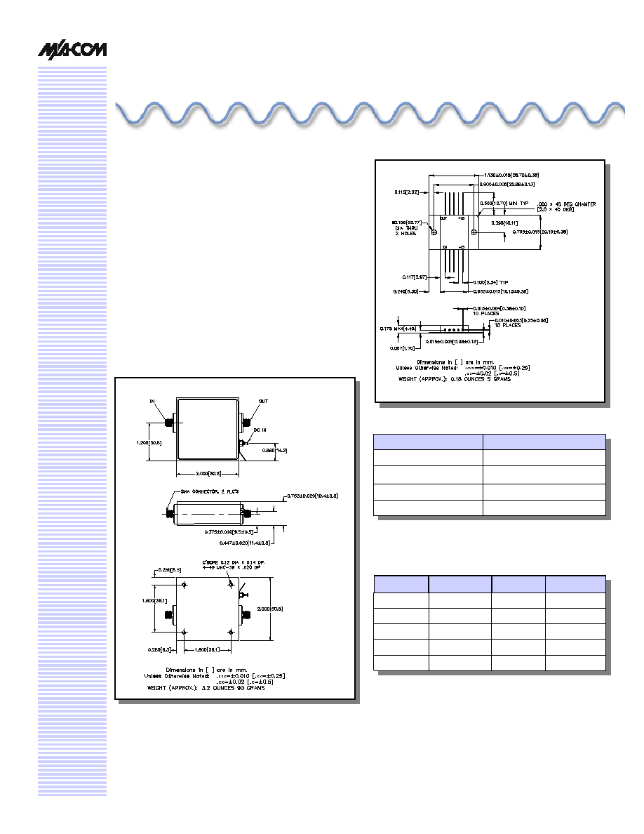
intercept amplifier. This amplifier is packaged in a flatpack
with flanges. Due to the internal power dissipation the
thermal rise should be minimized. The ground plane on the
PC board should be configured to remove heat from under
the package. AM-136 is ideally suited for use where a high
intercept, high reliability amplifier is required.
Pin Configuration
Pin #
Function
Pin #
Function
1
RF OUT
6
RF IN
2
GND
7
GND
3
GND
8
GND
4
GND
9
GND
5
Vbias
2
10
Vbias
2
2. Bias may be applied to either a single bias pin, or both bias
pins. If bias is applied to both bias pins, it is important that
potential ground loops be avoided, and that there is ade-
quate filtering on the bias lines.

High Performance Amplifier, 20 dB Gain, 10 - 200 MHz
AM-/AMC-136
Specifications subject to change without notice.
n
North America: Tel. (800) 366-2266
n
Asia/Pacific: Tel.+81-44-844-8296, Fax +81-44-844-8298
n
Europe: Tel. +44 (1344) 869 595, Fax+44 (1344) 300 020
Visit www.macom.com for additional data sheets and product information.
V 5.00
2
Electrical Specifications
3,4
T
A
= -55∞C to +85∞C Case Temperature
Parameter
Test Conditions
Frequency
Units
Min.
Typ.
Max.
Gain
50 MHz @ +25∞C
50 MHz
dB
19.2
20.4
20.8
Frequency Response
--
10 - 200 MHz
dB
--
--
±0.8
Gain Variation with
Temperature
--
10 - 200 MHz
dB
--
--
±1.0
1 dB Compression
Output Power
10 - 200 MHz
10 - 70 MHz
dBm
dBm
+23
+25
--
--
--
--
Noise Figure
--
10 - 200 MHz
dB
--
--
7.0
Reverse Transmission
--
10 - 200 MHz
dB
--
-28
-26
VSWR
--
10 - 200 MHz
10 - 70 MHz
Ratio
Ratio
--
--
--
--
2.5:1
1.7:1
Output IP
2
Two-tone inputs up to +10 dBm
10 - 200 MHz
10 - 70 MHz
dBm
dBm
+53
+57
--
--
--
--
Output IP
3
Two-tone inputs up to +10 dBm
10 - 200 MHz
10 - 70 MHz
dBm
dBm
+36
+44
--
--
--
--
Vbias
--
--
V
14.25
15
15.75
Ibias
Vbias = +15.0 VDC
--
mA
--
180
220
Power Dissipation
@ +15V Bias
--
W
--
2.7
--
Typical Performance Curves
Intermodulation Intercept
Gain vs. Frequency
3. All specifications apply when operated at +15 VDC, with 50 ohms source and load impedance.
4. Heat Sinking: Operation at case temperature above 95∞C is not recommended. Heat sinking adequate to dissipate 3.5W must
be provided in use. The flange should be screwed down to the heat sink, which should be RF ground.
19.0
20.0
21.0
22.0
3
5
10
20
50
100
200
300
Frequency (MHz)
Gain (dB)
+85∞C
+25∞C
-55∞C
60
64
68
72
3
5
10
20
50
100
200
300
Frequency (MHz)
Intercept (dBm)IP2
40
44
48
52
Intercept (dBm) IP3
IP2
IP3
High Performance Amplifier, 20 dB Gain, 10 - 200 MHz
AM-/AMC-136
Specifications subject to change without notice.
n
North America: Tel. (800) 366-2266
n
Asia/Pacific: Tel.+81-44-844-8296, Fax +81-44-844-8298
n
Europe: Tel. +44 (1344) 869 595, Fax+44 (1344) 300 020
Visit www.macom.com for additional data sheets and product information.
V 5.00
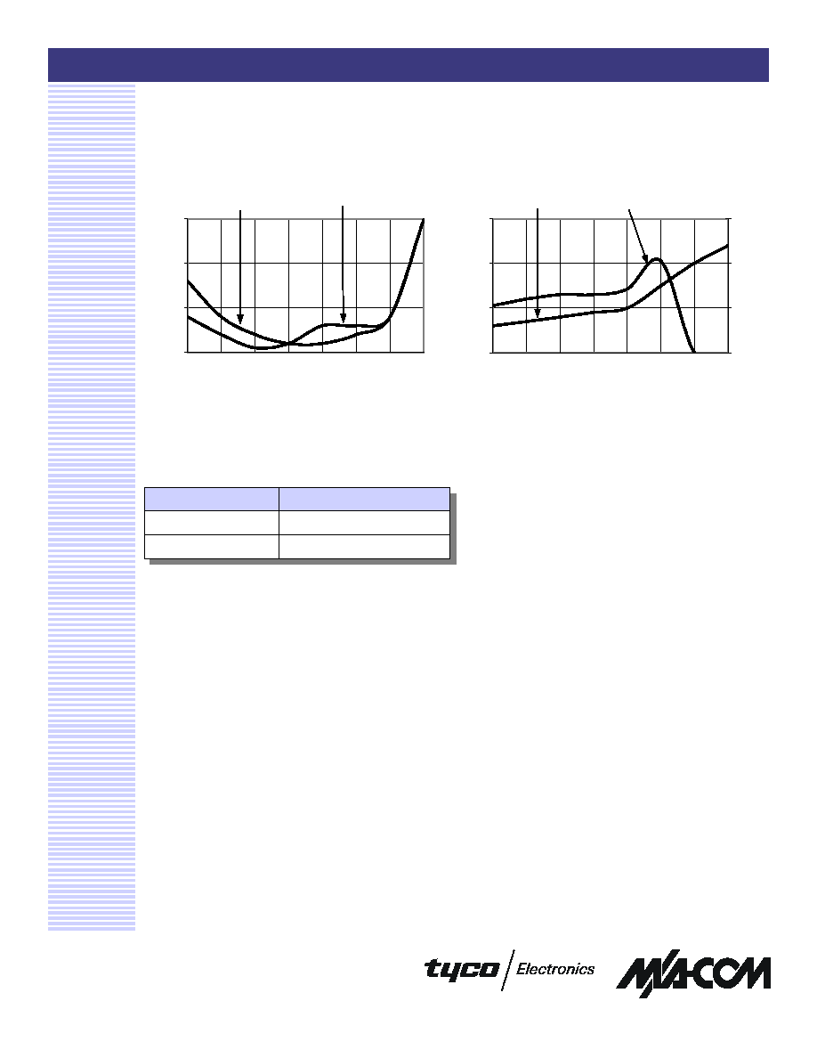
Typical Performance Curves
Noise Figure and 1 dB Compression
VSWR vs. Frequency
3
Ordering Information
Part Number
Package
AM-136 PIN
FP-9
AMC-136 SMA
C-25
1.00
1.50
2.00
2.50
3
5
10
20
50
100
200
300
Frequency (MHz)
VSWR
RF IN
RF OUT
4.5
5.0
5.5
6.0
3
5
10
20
50
100
200
300
Frequency (MHz)
Noise Figure (dB)
26
28
30
32
Output Power
Noise Figure
Output Power