Features
n
1.9 dB Typical Midband Noise Figure
n
+7 dBm Typical Midband Output Power
n
+20 dBm Typical Third Order Intercept
Description
M/A-COM's AM-143 is a coupler feedback amplifier with
low noise figure and high intercept points for the low bias
current. The use of coupler feedback minimizes noise figure
and current in a high intercept amplifier. This amplifier is
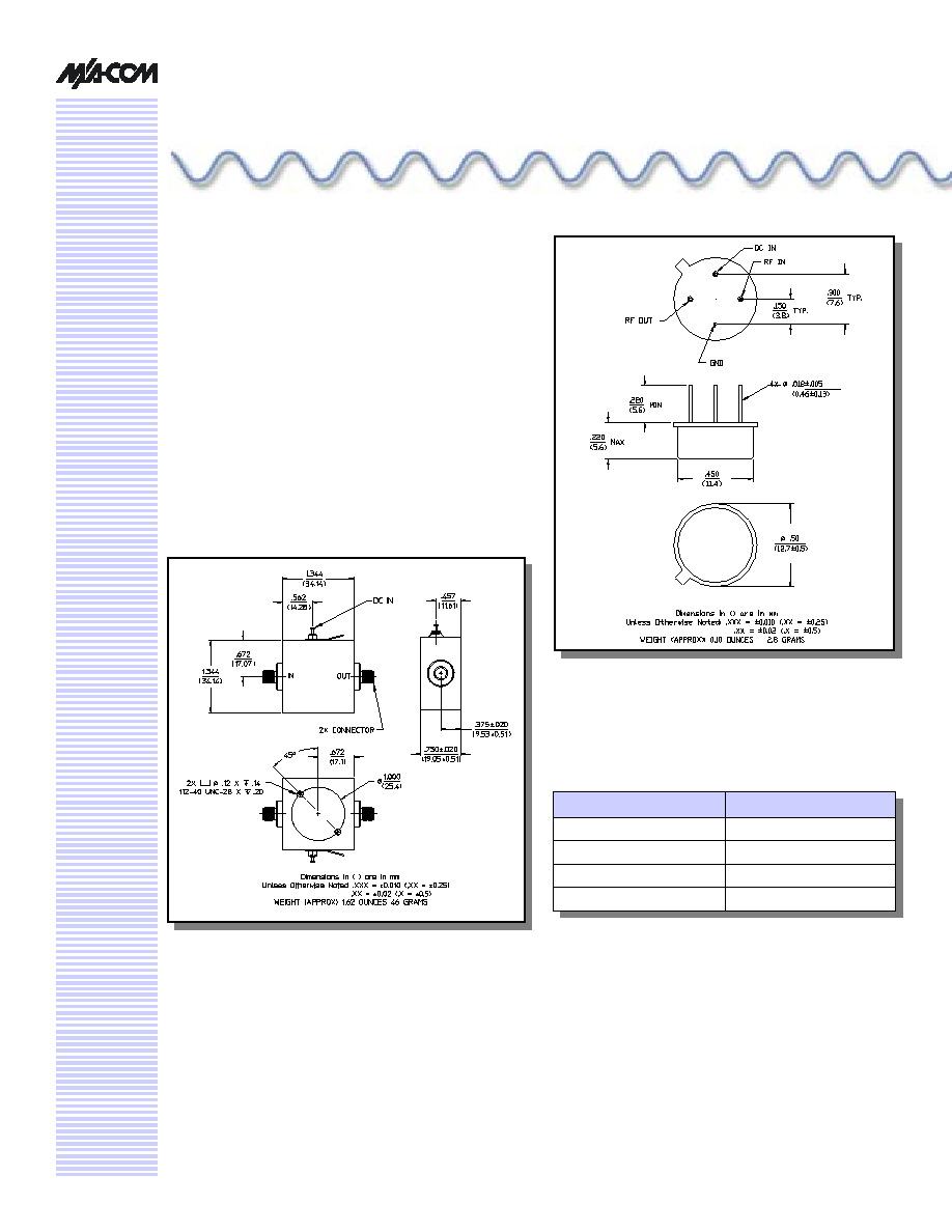
packaged in a TO-8 package. The ground plane on the PC
board should be configured to remove heat from under the
package. AM-143 are ideally suited for use where a low
noise, high reliability amplifier is required.
Low Noise Amplifier, 16 dB Gain,
5 - 500 MHz
AM-/AM
C-143
TO-8-1
C-32
Absolute Maximum Ratings
1
1. Operation of this device above any one of these
parameters may cause permanent damage.
Parameter
Absolute Maximum
Max. Input Power
+20 dBm
V
bias
+15.75 V
Operating Temperature
-55∞C to +85∞C
Storage Temperature
-65∞C to +125∞C
V 3.00
Low Noise Amplifier, 16 dB Gain, 5 - 500 MHz
AM-/AMC-143
Specifications subject to change without notice.
n
North America: Tel. (800) 366-2266
n
Asia/Pacific: Tel.+81-44-844-8296, Fax +81-44-844-8298
n
Europe: Tel. +44 (1344) 869 595, Fax+44 (1344) 300 020
Visit www.macom.com for additional data sheets and product information.
V 3.00
2
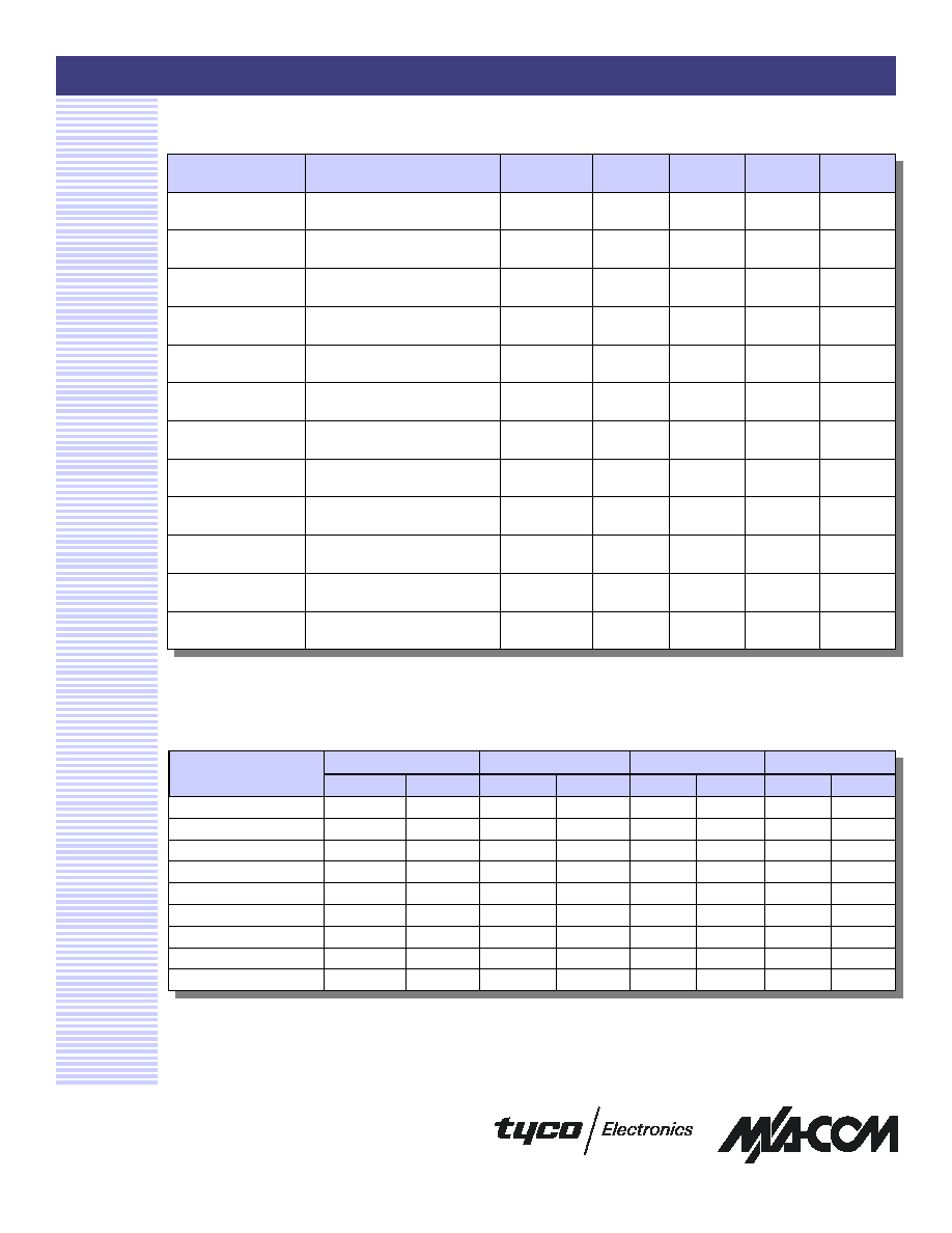
Electrical Specifications
2
T
A
= -55∞C to +85∞C Case Temperature
Parameter
Test Conditions
Frequency
Units
Min.
Typ.
Max.
Gain
@ +25∞C
50 MHz
dB
15.3
15.8
16.3
Frequency Response
--
5 - 500 MHz
dB
--
--
± 1.0
Gain Variation with
Temperature
--
5 - 500 MHz
dB
--
--
± 0.8
1 dB Compression
Output Power
5 - 500 MHz
dBm
+4
--
--
Noise Figure
--
5 - 500 MHz
5 - 100 MHz
dB
dB
--
--
--
--
3.5
2.7
Reverse Transmission
--
5 - 500 MHz
dB
--
-21
-16
VSWR
--
5 - 500 MHz
Ratio
--
--
2.5:1
Output IP
2
Two-tone inputs up to ≠10 dBm
5 - 500 MHz
dBm
+24
--
--
Output IP
3
Two-tone inputs up to ≠10 dBm
5 - 500 MHz
dBm
+16
--
--
Vbias
--
--
VDC
+14.5
+15.0
+15.5
Ibias
Vbias = +15.0 VDC
--
mA
--
13
15
Power Dissipation
@ +15.0V Bias
--
mW
--
200
--
2. All specifications apply when operated at +15 VDC, with 50 ohms source and load impedance.
S-Parameter Data
S11
S21
S12
S22
MAG
ANG
MAG
ANG
MAG
ANG
MAG
ANG
5
0.20
-60.7
5.90
-161.0
0.09
-160.5
0.32
-24.9
10
0.12
-63.8
6.07
-171.8
0.09
-172.6
0.27
-24.9
200
0.21
-130.6
6.00
126.7
0.10
119.8
0.26
-82.3
500
0.22
-142.9
6.11
36.8
0.10
43.3
0.20
-79.8
Frequency (MHz)
20
0.09
-65.3
6.16
-179.8
0.10
178.9
0.26
-17.4
50
0.10
-82.7
6.08
167.5
0.10
166.3
0.25
-28.0
100
0.14
-101.0
6.06
153.3
0.10
150.5
0.26
-49.3
300
0.23
-149.2
6.01
100.9
0.10
93.6
0.24
-104.5
400
0.20
-155.5
6.09
70.7
0.10
67.4
0.22
-100.5

Low Noise Amplifier, 16 dB Gain, 5 - 500 MHz
AM-/AMC-143
Specifications subject to change without notice.
n
North America: Tel. (800) 366-2266
n
Asia/Pacific: Tel.+81-44-844-8296, Fax +81-44-844-8298
n
Europe: Tel. +44 (1344) 869 595, Fax+44 (1344) 300 020
Visit www.macom.com for additional data sheets and product information.
V 3.00
Typical Performance Curves
Noise Figure
3
1 dB Compression
Intermodulation Intercept
Gain vs. Frequency
VSWR vs. Frequency
Ordering Information
Part Number
Package
AM-143 PIN
3
TO-8-1
AMC-143 SMA
Connectorized
3. Mounting kit part number AU00071 required for PCB
applications.
5
6
7
8
9
5
10
20
50
100
200
300
400
500
600
Frequency (MHz)
Ou
tp
u
t
P
o
wer
(d
Bm
)
14
15
16
17
3
5
10
20
50
100
200
300
400
500
600
Frequency (MHz)
Gain
(d
B)
+85∞C
+25∞C
-55∞C
1.0
1.5
2.0
2.5
3
5
10
20
50
100
200
300
400
500
600
Frequency (MHz)
VSWR
RF IN
RF OUT
1.5
2.0
2.5
3.0
5
10
20
50
100
200
300
400
500
Frequency (MHz)
Noi
se Fi
gur
e (
d
B)
+25∞C
+85∞C
15
20
25
30
3
5
10
20
50
100
200
300
400
500
600
Frequency (MHz)
In
te
rc
e
p
t (d
B
m
)
IP2 (f1+f2)
IP3