 | –≠–ª–µ–∫—Ç—Ä–æ–Ω–Ω—ã–π –∫–æ–º–ø–æ–Ω–µ–Ω—Ç: AT-119 | –°–∫–∞—á–∞—Ç—å:  PDF PDF  ZIP ZIP |
Parameter
Absolute Maximum
Maximum Input Power
+21 dBm
Supply Voltage V
CC
-1 V, + 8 V
ControlVoltage V
CTL
-1 V, V
CC
+0.5 V
Operating Temperature
-40∞C to +85∞C
Storage Temperature
-65∞C to +150∞C
Absolute Maximum Ratings
1
@ T
A
= +25 ∞C (unless otherwise specified)
1. Exceeding any one or a combination of these limits may
cause permanent damage.
Features
Single Positive Voltage Control 0 to +2.25 Volts
>50 dB Attenuation Range at 2.1 GHz
Low DC Power Consumption
Low Cost SOT-25 Plastic Package
Tape and Reel Packaging Available
Description
M/A-COM's AT-119 is a GaAs MMIC voltage variable
absorptive attenuator in a low cost, SOT-25 five-lead,
surface mount plastic package. M/A-COM fabricates the
AT-119 with a proven monolithic GaAs self-aligned gate
process that features full chip passivation for performance
and reliability
Applications
The AT-119 is ideally suited for applications that require
fine tuning, linear attenuation with voltage, and very low
power consumption.
Typical applications for the AT-119 include automatic gain
control circuits in satellite radio receivers and other wireless
receivers.
2.25 Volt Voltage Variable Absorptive
Attenuator - 40 dB, 1.8--2.5 GHz
A
T
-119
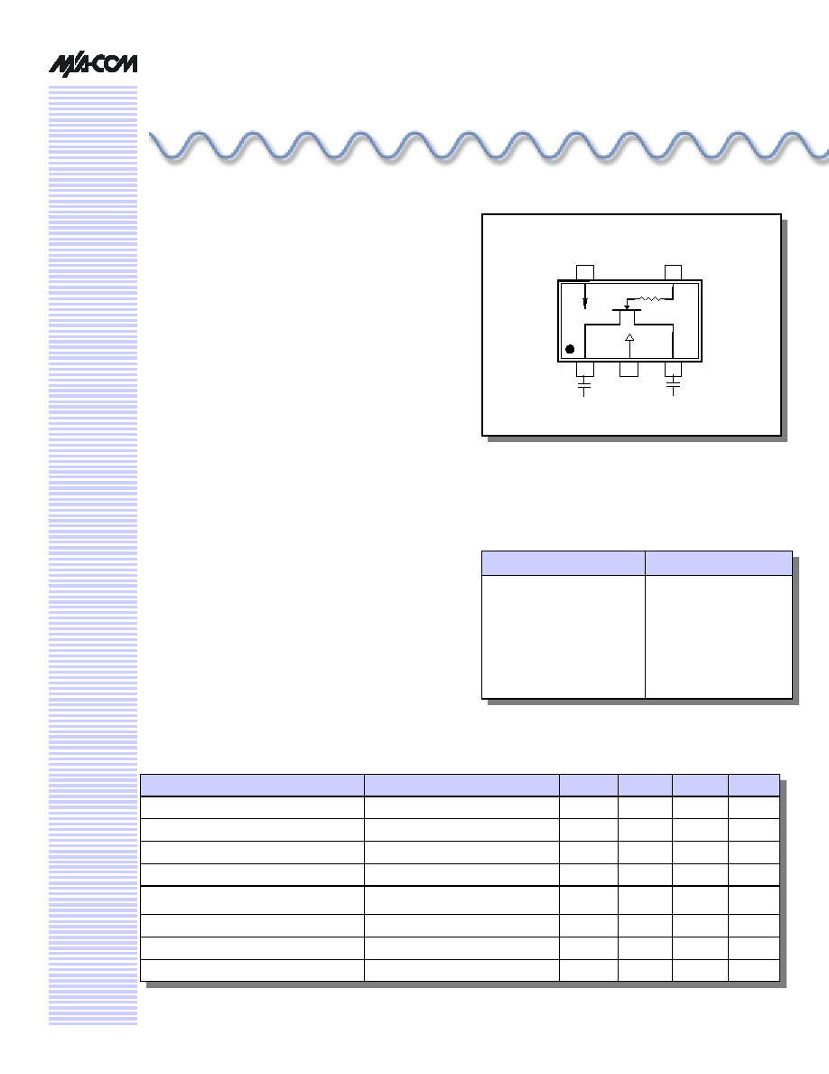
Functional Schematic
1. V
CC
= +3.3 V
DC
@ 50 µA max.
2. V
CTL
= 0 V
DC
to +3.3 VDC @ 50 µA max.
3. External DC blocking capacitors are required on all RF
ports.
Electrical Specifications @ T
A
= +25 ∞C, Frequency = 2.4 GHz, V
CC
= 3.3 V
DC
1
Parameters
Test Conditions
Units
Min
Typ
Max
Minimum Insertions Loss
V
CTL
= 2.25 V
DC
dB
3.0
3.2
Maximum Attenuation
V
CTL
= 0.5 V
DC
dB
37
Attenuation Slope
0.75 V
DC
< V
CTL
< 1.75 V
DC
dB/V
24
Return Loss
0.6 V
DC
< V
CTL
< 1.75 V
DC
dB
>12
Input Power for 1 dB Change in Attenua-
tion
0 V
DC
< V
CTL
< 3.0 V
DC
dBm
>10
Input 3
rd
Order Intercept Point
0 V
DC
< V
CTL
< 3.0 V
DC
dBm
>20
Switching Speed
50% V
CTL
to 10% / 90% RF
nSec
180
Transients
mV
10
V
CTL
= 3 V
DC,
In-Band
1. All measurements in a 50-
system unless otherwise specified. The RF ports must be blocked outside of the package from
ground or any other voltage.
3
RF
2
GND
1
RF
V
CTL
4
V
CC
5
100 pF
100 pF
2.25 Volt Voltage Variable Absorptive Attenuator, 40 dB, 1.8 - 2.5 GHz
AT-119
Specifications subject to change without notice.
North America: Tel. (800) 366-2266
Asia/Pacific: Tel.+81-44-844-8296, Fax +81-44-844-8298
Europe: Tel. +44 (1344) 869 595, Fax+44 (1344) 300 020
Visit www.macom.com for additional data sheets and product information.
0
5
10
15
20
25
30
35
40
45
50
55
60
500
1000
1500
2000
2500
3000
FREQUENCY (MHz)
+25 deg C
+85 deg C
-40 deg C
-6
-4
-2
0
2
4
6
0.0
0.5
1.0
1.5
2.0
2.5
3.0
CONTROL VOLTAGE (V
DC
)
1.8 GHz
2.1 GHz
2.4 GHz
-40
o
C
2
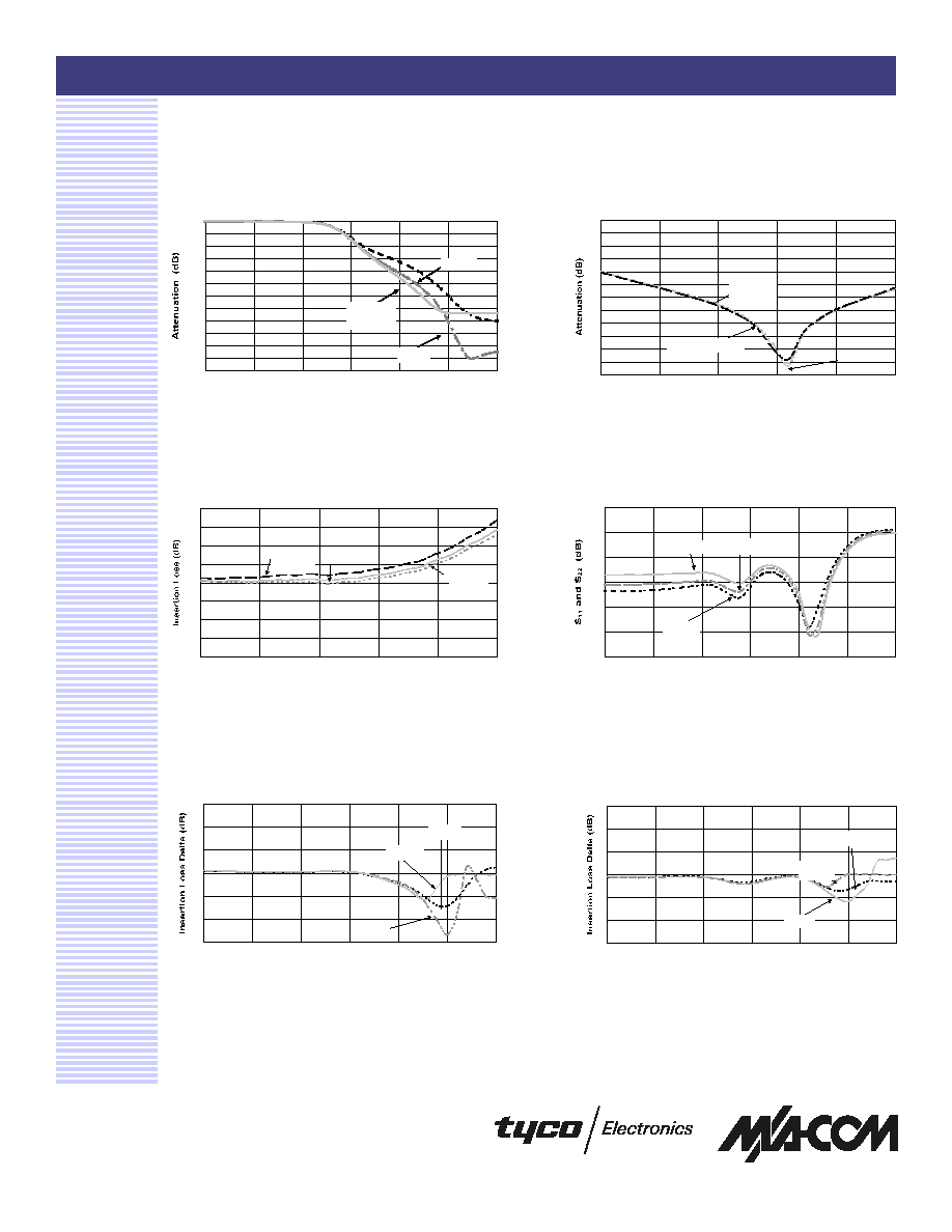
Attenuation vs. Control Voltage, +25 ∞C
Insertion Loss vs. Frequency @ 2.25
V
DC
for Control Voltage
Attenuation vs. Frequency @ 0.0 V
DC
for Control Voltage
Return Loss vs. Control Voltage
@ +25 ∞C
Typical Performance Curves
Insertion Loss Delta Normalized
to +25 ∞C
0.0
5.0
10.0
15.0
20.0
25.0
30.0
35.0
40.0
45.0
50.0
55.0
60.0
0.0
0.5
1.0
1.5
2.0
2.5
3.0
CONTROL VOLTAGE (Volts)
1.8 GHz
2.1 GHz
2.4 GHz
-30
-25
-20
-15
-10
-5
0
0.0
0.5
1.0
1.5
2.0
2.5
3.0
CONTROL VOLTAGE (V
DC
)
1.8 GHz
2.1 GHz
2.4 GHz
Insertion Loss Delta Normalized
to +25 ∞C
0.0
0.5
1.0
1.5
2.0
2.5
3.0
3.5
4.0
500
1000
1500
2000
2500
3000
FREQUENCY (MHz)
+25 deg C
+85 deg C
-40 deg C
-6
-4
-2
0
2
4
6
0.0
0.5
1.0
1.5
2.0
2.5
3.0
CONTROL VOLTAGE (V
DC
)
1.8 GHz
2.1 GHz
2.4 GHz
+85
o
C
2.25 Volt Voltage Variable Absorptive Attenuator, 40 dB, 1.8 - 2.5 GHz
AT-119
Specifications subject to change without notice.
North America: Tel. (800) 366-2266
Asia/Pacific: Tel.+81-44-844-8296, Fax +81-44-844-8298
Europe: Tel. +44 (1344) 869 595, Fax+44 (1344) 300 020
Visit www.macom.com for additional data sheets and product information.
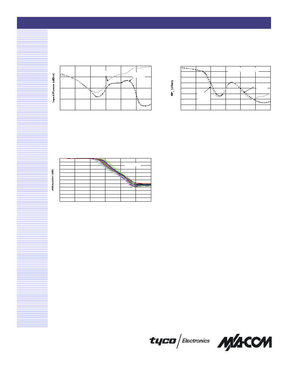
Typical Performance Curves (Cont'd)
Input Power for 1 dB Change in
Attenuation: +25 ∞C
Typical Device Variation,
Attenuation vs. V
CTL
Input IP
3
vs. Control Voltage: +25 ∞C
3
0
5
10
15
20
0.0
0.5
1.0
1.5
2.0
2.5
3.0
CONTROL VOLTAGE (V
DC
)
1.8 GHz
2.4
0
5
10
15
20
25
30
35
40
0
0.5
1
1.5
2
2.5
3
CONTROL VOLTAGE (V
DC
)
1.8 GHz
2.4 GHz
Input Power = 0 dBm
0
5
10
15
20
25
30
35
40
45
50
55
60
0.0
0.5
1.0
1.5
2.0
2.5
3.0
V
CTL
(V
DC
)
Freq = 2.4 GHz
2.25 Volt Voltage Variable Absorptive Attenuator, 40 dB, 1.8 - 2.5 GHz
AT-119
Specifications subject to change without notice.
North America: Tel. (800) 366-2266
Asia/Pacific: Tel.+81-44-844-8296, Fax +81-44-844-8298
Europe: Tel. +44 (1344) 869 595, Fax+44 (1344) 300 020
Visit www.macom.com for additional data sheets and product information.
Ordering Information
1. If specific reel size is required, consult factory for part
number assignment.
Part Number
Package
AT-119TR
Tape and Reel
1
AT-119TR-3000
3000 Piece Tape and Reel
AT-119SMB
Sample Board
SOT-25
1
SOT-25
1
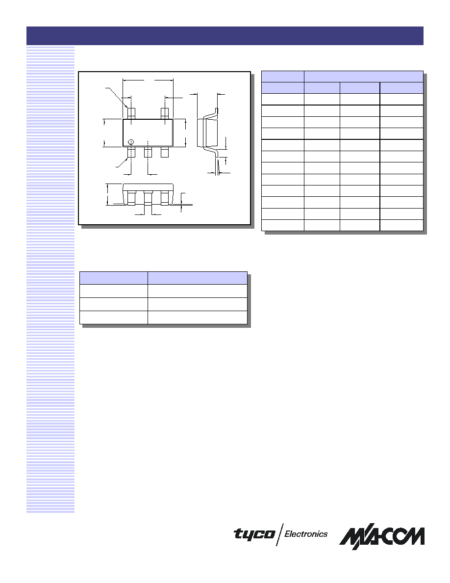
Dimensions
1. See JEDEC MO-178 VAR AA for additional dimensions and
tolerances
WZ X Y
D
PIN 5
e1
E1
PIN 5
e
A
A1
b
A2
L
∞
c
E
DIM
MIN
NOM
MAX
A
1.45
A1
0.15
A2
0.90
1.15
1.30
b
0.30
0.50
c
0.08
0.22
∞
∞
∞
∞
0∞
4∞
8∞
Measurement (mm)
D
2.90 basic
e
0.95 basic
e1
1.90 basic
E
2.80 basic
E1
1.60 basic
L
0.30
0.60
0.45
4