Digital Attenuator, 31 dB, 5-Bit, TTL Driver
DC - 2.0 GHz
AT15-0001
M/A-COM, Inc.
North America:
Tel. (800) 366-2266
s
Asia/Pacific: Tel. +81 (03) 3226-1671
s
Europe: Tel. +44 (1344) 869 595
Fax (800) 618-8883
Fax +81 (03) 3226-1451
Fax +44 (1344) 300 020
1
Specifications Subject to Change Without Notice.
V4.00
Features
Attenuation: 1-dB Steps to 31 dB
Low DC Power Consumption
Integral TTL Driver
50
Nominal Impedance
Description
M/A-COM's AT15-0001 is a GaAs FET 5-bit digital
attenuator with a 1-dB minimum step size and 31 dB
total attenuation. This attenuator and integral TTL driver
is in a 24-pin dual inline package. The AT15-0001 is
ideally suited for use where accuracy, fast switching,
very low power consumption and low intermodulation
products are required. Typical applications include
dynamic range setting in precision receiver circuits and
other gain/leveling control circuits.
Environmental screening is available. Contact the factory
for information.
Parameter
Test Conditions
Units
Minimum
Typical
Maximum
Reference Insertion Loss
DC - 0.5 GHz
dB
6.0
DC - 1.0 GHz
dB
6.5
DC - 2.0 GHz
dB
7.3
Attenuation Accuracy
2,3
Any Single Bit
DC - 1.0 GHz
± (0.2 dB + 2% of attenuation setting in dB) dB
DC - 2.0 GHz
± (0.25 dB + 2% of attenuation setting in dB) dB
Any Combination of Bits
DC - 1.0 GHz
± (0.2 dB + 2% of attenuation setting in dB) dB
DC - 2.0 GHz
± (0.3 dB + 2% of attenuation setting in dB) dB
VSWR
DC - 0.5 GHz
1.3:1
DC - 1.0 GHz
1.4:1
DC - 2.0 GHz
1.7:1
Trise, Tfall
10% RF to 90% RF
nS
5
Ton, Toff
50% Control to 90%/10% RF
nS
30
Transients
In-band
mV
220
1 dB Compression
Input Power
0.05 GHz
dBm
+20
Input Power
0.5 - 2.0 GHz
dBm
+27
Input IP
3
For two-tone input power
0.05 GHz
dBm
+40
up to +5 dBm
0.5 - 2.0 GHz
dBm
+40
Input IP
2
For two-tone input power
0.05 GHz
dBm
+60
up to +5 dBm
0.5 - 2.0 GHz
dBm
+75
V
CC
V
4.5
5.0
5.5
V
EE
V
-16.5
-10.8
I
CC
V
CC
= 4.5 to 5.5 V
mA
10
Vctl = 0 to 0.8 V, or V
CC
- 2.1 V to V
CC
I
EE
V
EE
= -16.5 to -10.8 V
mA
8.0
V
EE
= -12.0 V
mA
5.0
Vctl
Logic 0 (TTL)
V
0.0
0.8
Logic 1 (TTL)
V
2.0
5.0
Input Leakage Current
Low
0 to 0.8 V
µA
1.0
High
2.0 to 5.0 V
µA
1.0
Typical Electrical Specifications
1
,
T
A
= - 55∞C to +85∞C
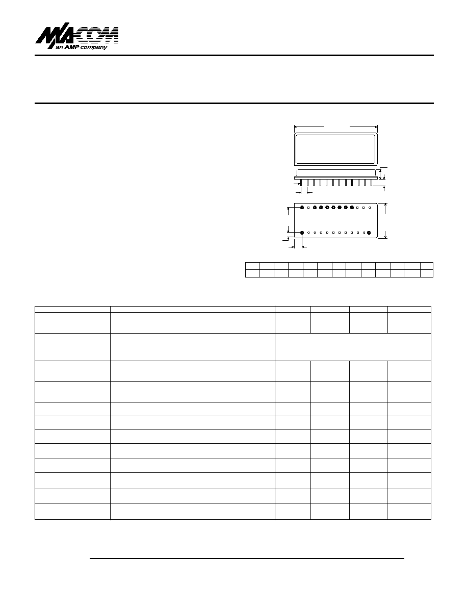
PIN 1
PIN 13
0.600
(15.2)
0.14
(3.6
±
0.5)
0.10
(2.5
±
0.5)
0.80
(20.3
±
0.5)
0.100 TYP
(2.4)
0.018
±
0.005
(0.46
±
0.13)
DIA 24 PINS
0.120 MIN
(3.0)
0.200 MAX
(5.1)
RF1
RF2
+V C R 16 1 2 4 8
1.37
(34.8
±
0.5)
DI-3
Dimensions in ( ) are in mm. Unless otherwise noted:
.xxx = ± 0.010 (.xx = ±0.25)
q
q
q
q
1. All specifications apply when operated with bias voltages of +5 V for V
CC
and -16.5 V to -10.8 V for V
EE
, and 50
impedance at all ports unless otherwise specified.
2. Above reference insertion loss.
3. This attenuator is guaranteed monotonic.
4. Replaces AT-104.
1
2
3
4
5
6
7
8
9
10-12 13 14- 23 24
+5 V GND -12 V GND C16
C1
C2
C4
C8 GND RF2 GND RF1
Pin Configuration
Digital Attenuator, 31 dB, 5-Bit, TTl Driver
AT15-0001
V4.00
M/A-COM, Inc.
North America:
Tel. (800) 366-2266
s
Asia/Pacific: Tel. +81 (03) 3226-1671
s
Europe: Tel. +44 (1344) 869 595
Fax (800) 618-8883
Fax +81 (03) 3226-1451
Fax +44 (1344) 300 020
2
Specifications Subject to Change Without Notice.
0.0
0.5
1.0
1.5
2.0
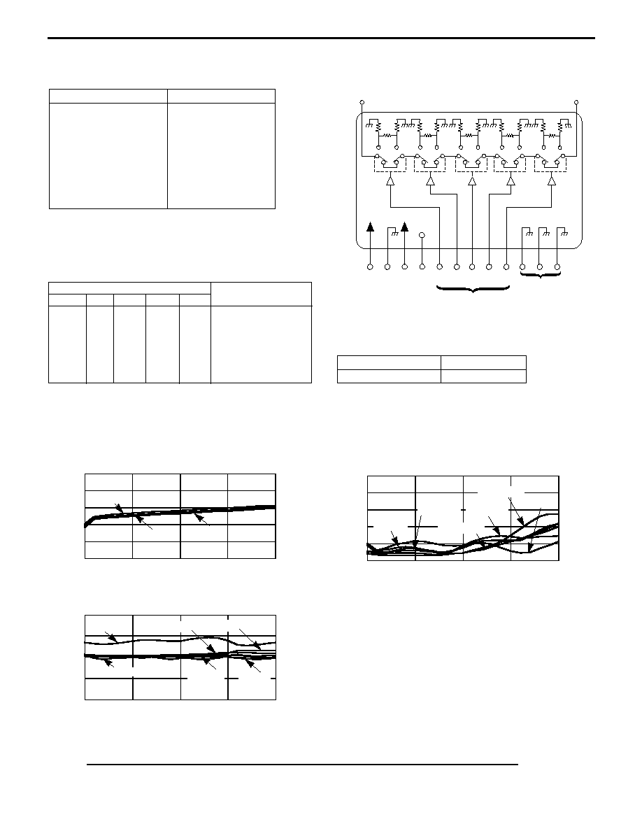
Functional Schematic
Parameter
Absolute Maximum
Maximum Input Power
DC - 0.5 GHz
0.5 - 2.0 GHz
Supply Voltages
V
CC
V
EE
Control Voltage
Operating Temperature
Storage Temperature
Absolute Maximum Ratings
1
Typical Performance
1. Operation of this device above any one of these
parameters may cause permanent damage.
REFERENCE INSERTION LOSS
VS
FREQUENCY
VSWR
VS
FREQUENCY
INSERTION LOSS (dB)
+25∞C
-55∞C
4 dB Bit State
16 dB Bit State
8 dB Bit State
2 dB Bit State
1 dB Bit State
0.0
0.5
1.0
1.5
2.0
2.0
1.8
1.6
1.4
1.2
1.0
10
8
6
4
2
0
VSWR
FREQUENCY (GHz)
FREQUENCY (GHz)
Control Inputs
C16
C8
C4
C2
C1
Attenuation
0
0
0
0
0
Reference
0
0
0
0
1
1 dB
0
0
0
1
0
2 dB
0
0
1
0
0
4 dB
0
1
0
0
0
8 dB
1
0
0
0
0
16 dB
1
1
1
1
1
31 dB
0 = TTL Low
1 = TTL High
2. Contact the factory for standard or custom screening
requirements.
Truth Table
+27 dBm
+34 dBm
-0.5 V to +7.0 V
-18 V to +0.5 V
-0.5 V to V
CC
+ 0.5 V
-55∞C to +125∞C
-65∞C to +150∞C
ATTENUATION ACCURACY
VS
FREQUENCY
(1, 2, 4, 8 and 16 dB Bits and Full Attenuation)
DEVIATION FROM NOMINAL
ATTENUATION (dB)
1 dB Bit
2 dB Bit
4 dB Bit
8 dB Bit
16 dB Bit
0.0
0.5
1.0
1.5
2.0
1.0
0.5
0
-0.5
-1.0
FREQUENCY (GHz)
Ordering Information
2
Part Number
Package
AT15-0001
Dual Inline
RF 1
+5V
16 dB
GND
GND
1 dB
2 dB
4 dB
8 dB
RF 2
-12V N/C 16
1
2
4
8
TTL
CONTROL INPUT
+85∞C
Full Attenuation
Reference
Loss State