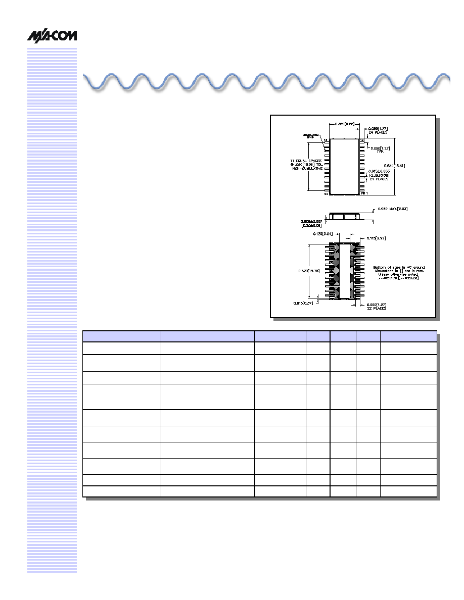
Digital Attenuator, 31.5 dB, 6-Bit,
TTL Driver, DC - 2.0 GHz
AT20
-
0107
CR-13
V 4.00
Electrical Specifications
2
: T
A
= +25∞C
Features
n
Attenuation: 0.5 dB Steps to 31.5 dB
1
n
Temperature Stability: ±0.18 dB from ≠40∫C to +85∫C
Typ.
n
Low DC Power Consumption
n
Surface Mount Package
n
Integral TTL Driver
n
High Intercept Point
n
Low Cost/High Performance
Description
M/A-COM's AT20-0107 is a GaAs FET 6-bit digital
attenuator with a 0.5 dB minimum step size and a 31.5 dB
total attenuation. This attenuator and integral TTL driver is
in a ceramic 24-lead surface mount package. The AT20-
0107 is ideally suited for use where accuracy, fast speed,
very low power consumption and low intermodulation
products are required. Typical applications include dynamic
range setting in precision receiver circuits and other gain/
leveling control circuits. Available with enhanced perform-
ance as fully hermetic version. Environmentally screenable
as P/N AT-107.
Parameter
Test Conditions
Frequency
Units
Min
Typ.
Max
Insertion Loss
--
DC - 2.0 GHz
dB
--
3.2
3.8
Attenuation Accuracy
3,4
Any Bit or Combination of Bits
DC - 2.0 GHz
dB
--
--
+(.3 +7% of atten.)
-(.2 +1% of atten.)
VSWR
Full Range
DC - 2.0 GHz
Ratio
--
--
1.8:1
Trise, Tfall
Ton, Toff
Transients
10% to 90%
50% Control to 90%/10% RF
In-band (peak to peak)
--
--
--
nS
nS
mV
--
--
--
50
150
50
--
--
--
1 dB Compression
5
Input Power
Input Power
50 MHz
0.5 - 2.0 GHz
dBm
dBm
--
--
+21
+29
--
--
Input IP
3
5
Two Tone Inputs up to +5 dBm
50 MHz
0.5 - 2.0 GHz
dB
dB
--
--
+35
+48
--
--
Input IP
2
5
Two Tone Inputs up to +5 dBm
50 MHz
0.5 - 2.0 GHz
dB
dB
--
--
+75
+79
--
--
Vcc
-Vee
--
--
--
--
V
V
4.5
-8.0
5.0
--
5.5
-5.0
Icc
Vcc = 4.5 to 5.5V
--
mA
--
--
6.0
-Iee
-Vee = -5.0 to -8.0V
--
mA
--
--
1.0
1.
Above reference insertion loss.
2.
All specifications apply when operated with bias voltages of +5V for V
CC
and ≠5.0 V to ≠8.0 V for V
EE
and 50O impedance at all
ports unless otherwise stated.
3.
This attenuator is guaranteed monotonic.
4.
For the attenuator to meet the guaranteed specifications, it is necessary to have a DC return on either RF1 or RF2. The DC
return can be either a 10KO resistor, or an RF choke.
5.
V
EE
= -5 V for the typical numbers given.
Digital Attenuator, 31.5 dB, 6-Bit, TTL Driver, DC - 2.0 GHz
AT20-0107
Specifications subject to change without notice.
n
North America: Tel. (800) 366-2266
n
Asia/Pacific: Tel.+81-44-844-8296, Fax +81-44-844-8298
n
Europe: Tel. +44 (1344) 869 595, Fax+44 (1344) 300 020
Visit www.macom.com for additional data sheets and product information.
V 4.00
2
Absolute Maximum Ratings
6
Parameter
Absolute Maximum
Max. Input Power
0.05 GHz
0.5 - 2.0 GHz
+27 dBm
+34 dBm
+Vcc
+5.5V
-Vee
-8.5V
Control Voltage
-0.5V to V
CC
+0.5V
Operating Temperature
-40∞C to +125∞C
Storage Temperature
-65∞C to +150∞C
6. Operation of this device above any one of these parameters
may cause permanent damange.
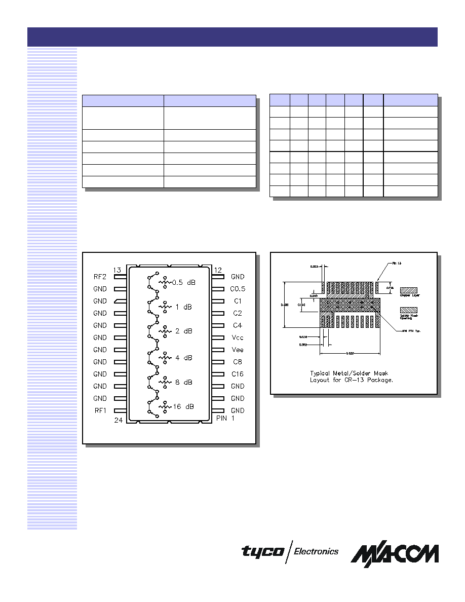
Truth Table
C16
C8
C4
C2
C1 C0.5
Attenuation
0
0
0
0
0
0
Loss, Reference
0
0
0
0
0
1
0.5 dB
0
0
0
0
1
0
1.0 dB
0
0
0
1
0
0
2.0 dB
0
0
1
0
0
0
4.0 dB
0
1
0
0
0
0
8.0 dB
1
0
0
0
0
0
16.0 dB
1
1
1
1
1
1
31.5 dB
0 = TTL Low; 1 = TTL High
Functional Schematic (Top View)
PCB Layout
Digital Attenuator, 31.5 dB, 6-Bit, TTL Driver, DC - 2.0 GHz
AT20-0107
Specifications subject to change without notice.
n
North America: Tel. (800) 366-2266
n
Asia/Pacific: Tel.+81-44-844-8296, Fax +81-44-844-8298
n
Europe: Tel. +44 (1344) 869 595, Fax+44 (1344) 300 020
Visit www.macom.com for additional data sheets and product information.
V 4.00
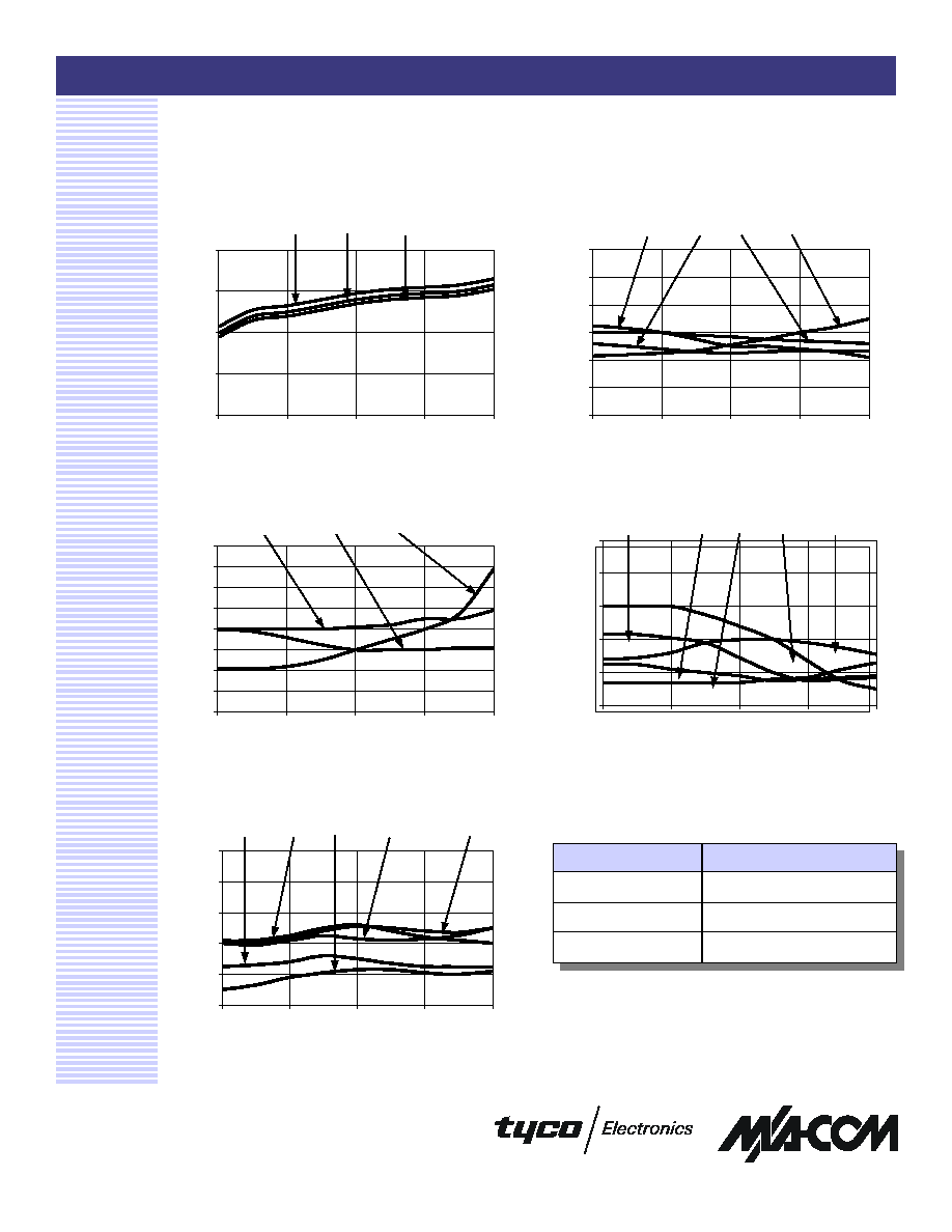
Typical Performance Curves
Attenuation Accuracy vs. Frequency
Insertion Loss vs. Frequency
Attenuation Accuracy vs. Frequency
3
RF1 VSWR vs. Frequency
RF2 VSWR vs. Frequency
Ordering Information
Part Number
Package
AT20-0107
Bulk Packaging
AT20-0107TR
Tape and Reel (1K Reel)
AT20-0107-TB
Unit mounted on a test board
0
1
2
3
4
0
0.5
1
1.5
2
Frequency (GHz)
Loss (dB)
+85 ∞C
-40 ∞C
+25 ∞C
-0.6
-0.4
-0.2
0
0.2
0.4
0.6
0
0.5
1
1.5
2
Frequency (GHz)
Deviation (dB)
1 dB
2 dB
4 dB
0.5 dB
-0.8
-0.6
-0.4
-0.2
0
0.2
0.4
0.6
0.8
0
0.5
1
1.5
2
Frequency (GHz)
Deviation (dB)
31.5 dB
8 dB
16 dB
1
1.2
1.4
1.6
1.8
2
0
0.5
1
1.5
2
Frequency (GHz)
Deviation (dB)
Loss & 0.5 dB
2 dB
1 dB
4 dB
8 & 16 dB
1
1.2
1.4
1.6
1.8
2
0
0.5
1
1.5
2
Frequency (GHz)
Deviation (dB)
Loss & 0.5 dB
1 & 2 dB
16 dB
4 dB
8 dB