Digital Attenuator, 3 Bit, Single Control, 28 dB, 0.5 - 2 GHz
AT-242
M/A-COM Division of AMP Incorporated
3
North America: Tel. (800) 366-2266, Fax (800) 618-8883
3
Asia/Pacific: Tel.+85 2 2111 8088, Fax +85 2 2111 8087
3
Europe: Tel. +44 (1344) 869 595, Fax+44 (1344) 300 020
www.macom.com
AMP and Connecting at a Higher Level are trademarks.
Specifications subject to change without notice.
V2.00
Features
∑
Single Control CMOS Logic for each bit
∑
Positive Supply +3 to +5 Volts
∑
Low Cost SOIC-8 Plastic Package
∑
Tape and Reel Packaging Available
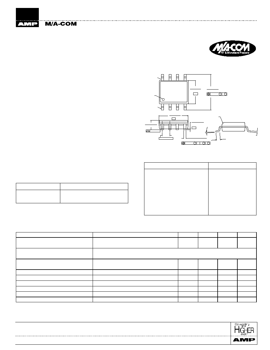
SOIC-8
1
Electrical Specifications: T
A
= +25∞C
1, 2
Digital Attenuator, 3 Bit, Single Control
28 dB, 0.5 - 2 GHz
AT-242
Parameter
Test Conditions
Units
Min.
Typ.
Max.
Reference Insertion Loss
0.5 - 1.0 GHz
dB
1.4
1.6
0.5 - 2.0 GHz
dB
1.7
1.9
Attenuation Accuracy
0.5 - 1.0 GHz ± (0.15 dB +3% of Attenuation Setting in dB) dB
0.5 - 2.0 GHz ± (0.3 dB = +8% of Attenuation Setting in dB) dB
VSWR
0.5 - 1.0 GHz
1.3:1
±0.8
0.5 - 2.0 GHz
1.6:1
±1.5
P
1dB
Input Power (Vs = +5V) 900 MHz
dBm
25
T
rise
, T
fall
10% to 90% RF, 90% to 10% RF
µ
S
290
T
on
, T
off
50% Control to 90% RF, Control to 10% RF
µ
S
300
Transients
In-band
mV
260
IP
2
Measured Relative to Input Power
2
dBm
75
IP
3
Measured Relative to Input Power
2
dBm
45
Description
M/A-COM's AT-242 is a 3 bit, 4 dB step GaAs MMIC digital
attenuator in a low cost SOIC 8-lead surface mount plastic
package. The AT-242 is ideally suited for use where high
accuracy, very low power consumption and low intermodula-
tion products are required. Typical applications include radio,
cellular, wireless LANs, GPS equipment and automatic gain/
level control circuits.
The AT-242 is fabricated with a GaAs MMIC using a mature
1-micron process. The process features full chip passivation for
increased performance and reliability.
Ordering Information
Part Number
Package
AT-242
SOIC-8 Lead Plastic
AT-242TR
Forward Tape and Reel
1
1. If specific reel size is required, consult factory for part number
assignment.
1.
All measurements at 1 GHz 5Vdc in a 50
system unless otherwise specified. The RF ports must be blocked out side of the package from
ground or any other voltage. Insertion Loss varies at 0.003 dB/∞C.
2.
For two-tone input power up to +10 dBm
Parameter
Absolute Maximum
Maximum Input Power
50 MHz
+27 dBm
500 - 2000 MHz
+34 dBm
Supply Voltage
-1V, +8V
Control Voltage
-1V, Vsupply +0.5V
Operating Temperature
-40∞C to +85∞C
Storage Temperature
-65∞C to +150∞C
Absolute Maximum Ratings
1
1.
Exceeding any one or a combination of these limits may cause
permanent damage.
(.19/.25)
CHAMFER
(OPTIONAL)
(0.40/1.27)
.016/.050
0∞/80∞
-B-
BSC.
-C-
-A-
.010(.25)
C A
B
M
M
S
.050(1.27)
Oreintation
Mark
.1497/.1574
(3.80/4.00)
M
M B
.010(.25)
.2284/.2440
(5.80/6.20)
.0532/.0688
(1.35/1.75)
.004(0.10)
.0075/.0098
PIN 8
PIN 1
.013/.020 (8 PL)
(.33/.51)
.0040/.0098
(.10/.25)
.1890/.1968
(4.80/5.00)
1. Dimensions are in inches/mm.
Digital Attenuator, 3 Bit, Single Control, 28 dB, 0.5 - 2 GHz
AT-242
M/A-COM Division of AMP Incorporated
3
North America: Tel. (800) 366-2266, Fax (800) 618-8883
3
Asia/Pacific: Tel.+85 2 2111 8088, Fax +85 2 2111 8087
3
Europe: Tel. +44 (1344) 869 595, Fax+44 (1344) 300 020
www.macom.com
AMP and Connecting at a Higher Level are trademarks.
Specifications subject to change without notice.
V2.00
-7.0
-6.0
-5.0
-4.0
-3.0
-2.0
-1.0
0.0
1.0
2.0
0.1
0.6
1.1
1.5
2.0
2.5
3.0
FREQUENCY (Ghz)
NOMINAL ATTENUATION (dB)
28 dB
16 dB
8 dB
4 dB
0.0
1.0
2.0
3.0
4.0
5.0
6.0
7.0
0.1
0.6
1.1
1.5
2.0
2.5
3.0
FREQUENCY (Ghz)
VSWR
Ins. Loss
28 dB Atten.
16 dB Atten.
-30
-28
-26
-24
-22
-20
-18
-16
-14
-12
-10
-8
-6
-4
-2
0
0.1
0.6
1.1
1.5
2.0
2.5
3.0
FREQUENCY (Ghz)
ATTENUATION (dB)
0.0
0.2
0.4
0.6
0.8
1.0
1.2
1.4
1.6
1.8
0.1
0.6
1.1
1.5
2.0
2.5
3.0
FREQUENCY (Ghz)
LOSS (dB)
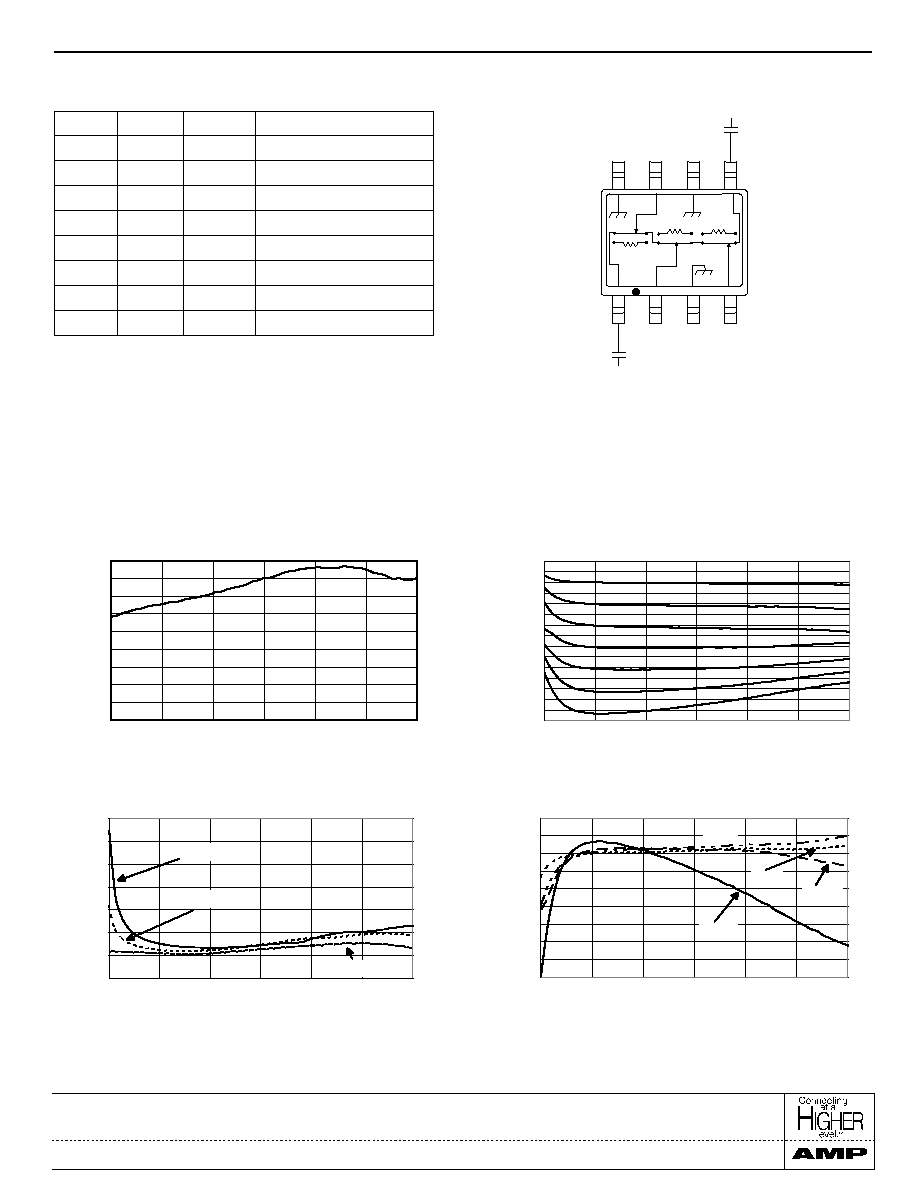
Typical Performance Curves
Insertion Loss vs. Frequency
Attenuation vs. Frequency
VSWR vs Frequency
Attenuation Accuracy vs. Frequency
Functional Schematic
1, 2, 3
1. V
s
= -3 V
DC
- 5 V
DC
@ 50 µA max.
2. V
s
can be applied to RF1 or RF2 through a 10K
pull-up resistor.
3. External DC blocking capacitors are required on all RF ports.
4. 39 pF used for data measurement.
V1
V2
V3
Attenuation (dB)
1
1
1
Reference I.L.
1
0
1
4
1
1
0
8
1
0
0
12
0
1
1
16
0
0
1
20
0
1
0
24
0
0
0
28
Truth Table
Logic 1 = Vs ± 0.2 V
Logic 0 = 0 ± 0.2C
8
7
6
5
1
3
2
4
GND
V3
GND
RF2
RF1
V2
GND
V1
8
4
16
(GHz)
(GHz)
(GHz)
(GHz)