North America: Tel. (800) 366-2266, Fax (800) 618-8883
Asia/Pacific: Tel.+81-44-844-8296, Fax +81-44-844-8298
Europe: Tel. +44 (1344) 869 595, Fax+44 (1344) 300 020
Specifications subject to change without notice.
Visit www.macom.com for additional data sheets and product information.
V 4.0
Features
∑
Single Voltage Control 0 to -3 Volts
∑
25 dB Attenuation Range at 0.9 GHz
∑
Low DC Power Consumption
∑
Low Cost SOT-25 Plastic Package
∑
Tape and Reel Packaging Available
SOT-25
Electrical Specifications: T
A
= +25∞C
1
=
=
=
=
Parameter
Test Conditions
Units
Min.
Typ.
Max.
Insertion Loss
DC - 2.0 GHz
dB
3.6
4.2
Attenuation
DC - 1.0 GHz
dB
23
25
1.0 - 2.0 GHz
dB
18
20
Flatness (Peak-to-Peak)
DC - 1.0 GHz
dB
±7
±10
1.0 - 2.0 GHz
dB
±5
±8
VSWR
DC - 2.0 GHz
3:1
T
rise
, T
fall
10% to 90% RF, 90% to 10% RF
nS
10
T
on
, T
off
50% Control to 90% RF, Control to 10% RF
nS
20
Transients
In-band
mV
10
Description
M/A-COM's AT-255 is a GaAs MMIC voltage variable
absorptive attenuator in a low cost SOT-25 surface mount
plastic package. The AT-255 is ideally suited for use where
variable attenuation fine tuning and very low power
consumption are required.
Typical applications include radio, cellular, GPS equipment and
automatic gain/level control circuits.
The AT-255 is fabricated using a mature 1-micron GaAs
MESFET process. The process features full chip passivation for
increased performance and reliability.
Ordering Information
Part Number
Package
AT-255
SOT-25 Plastic
AT-255TR
Forward Tape and Reel
1
1. Reference Application Note M513 for reel size information.
1. All measurements at 1 GHz in a 50
system unless otherwise specified. Insertion Loss varies 0.003 dB/∞C.
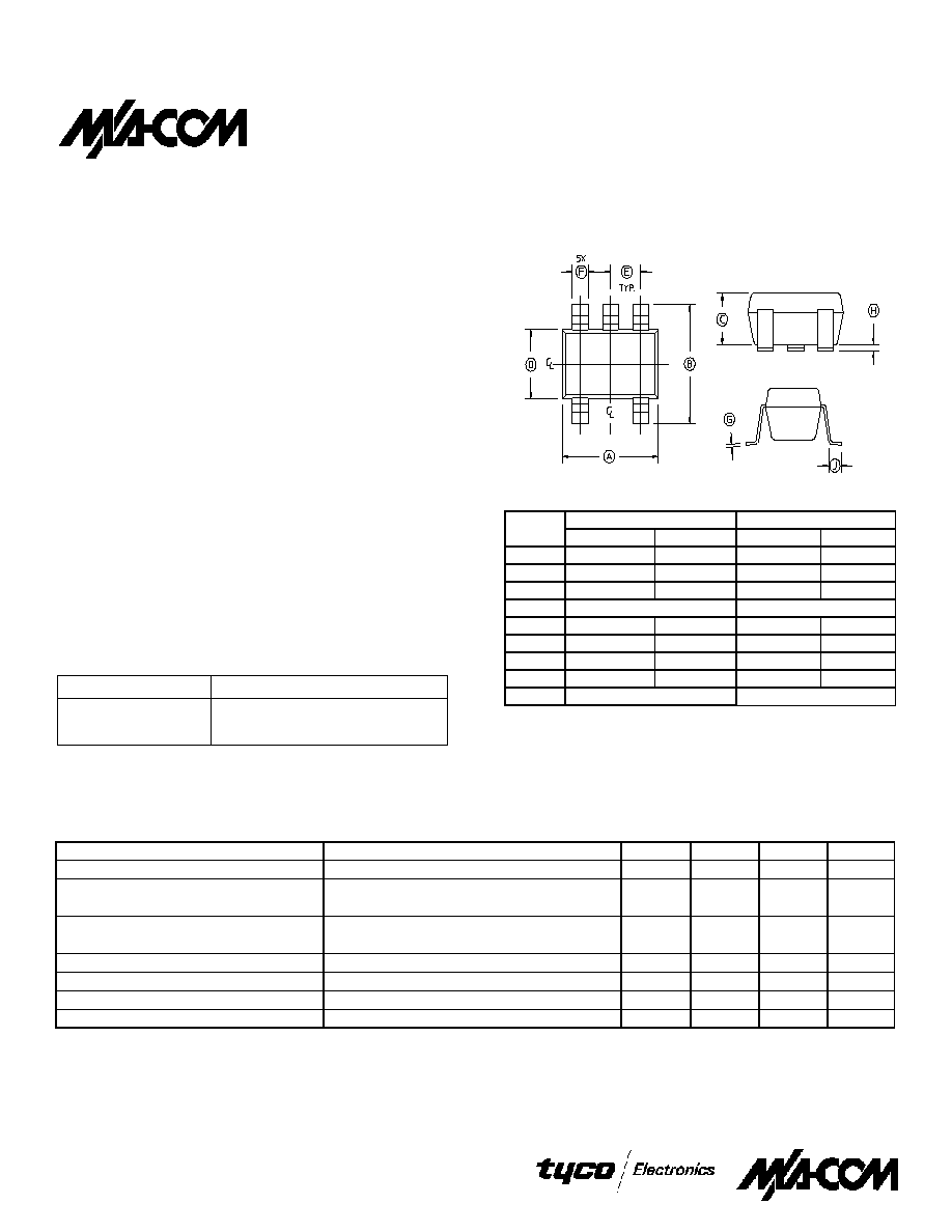
INCHES
MILLIMETERS
DIM
MIN
MAX
MIN
MAX
A
.106
.122
2.70
3.10
B
.100
.118
2.54
3.00
C
.051
1.30
D
.063 REF.
1.60 REF.
E
.032
.043
.80
1.10
F
.014
.020
.35
.50
G
.003
.08
H
.000
.006
.00
.15
J
.018 REF.
.45 REF
Note: 1. Leads Coplanarity should be 0.003 (0.08) max.
AT-255
3Volt Voltage Variable Attenuator
25 dB, DC - 2.5 GHz
1
North America: Tel. (800) 366-2266, Fax (800) 618-8883
Asia/Pacific: Tel.+81-44-844-8296, Fax +81-44-844-8298
Europe: Tel. +44 (1344) 869 595, Fax+44 (1344) 300 020
Specifications subject to change without notice.
Visit www.macom.com for additional data sheets and product information.
V 4.0
0
5
10
15
20
25
30
-3
-2
-1
0
CONTROL VOLTAGE (VOLTS)
C
O
MPR
ESSI
ON
POI
N
T (dBm)
50MHz
500MHz
INPUT IP3 vs CONTROL VOLTAGE
0
5
10
15
20
25
30
35
40
45
-3
-2
-1
0
CONTROL VOLTAGE (VOLTS)
IP3
(
d
Bm)
500 MHz
50MHz
-35
-30
-25
-20
-15
-10
-5
0
0
0.5
1
1.5
2
2.5
3
FREQUENCY (GHz)
ATTENUATIO
N
(dB)
Q
-25
-20
-15
-10
-5
0
-3
-2
-1
0
CONTROL VOLTAGE (VOLTS)
RE
T
URN LO
S
S
(dB
)
-4
-3
-2
-1
0
0
1
2
3
4
FREQUENCY(GHz)
ATTEN
U
A
TION
(
d
B)
-35
-30
-25
-20
-15
-10
-5
0
-3
-2
-1
0
CONTROL VOLTAGE (VOLTS)
ATTEN
U
A
TION
(
d
B)
2.5GHz
1.0GHz
50MHz
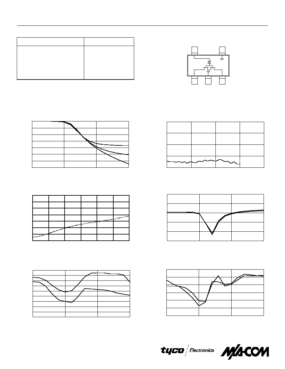
Typical Performance Curves
Relative Attenuation vs. Control Voltage
Insertion Loss vs. Frequency
Maximum Relative Attenuation vs. Frequency
Return Loss vs. Control @ 900 MHz
Functional Schematic
1
Parameter
Absolute Maximum
Maximum Input Power
+21 dBm
Control Voltage V
C
-8V, +0.5V
Operating Temperature
-40∞C to +85∞C
Storage Temperature
-65∞C to +150∞C
Absolute Maximum Ratings
1
1. Exceeding any one or a combination of these limits may cause
permanent damage.
1. V
CC
= 0 V
DC
to -3 V
DC
@ 50 µA max.
Input IP3 vs. Control Voltage
Input P1dB vs. Control Voltage
5
4
1
3
2
RF
GND
Vc
RF
GND
2
3 Volt Voltage Variable Attenuator, 25 dB, DC - 2.5 GHz
AT-255