Part No.
Package
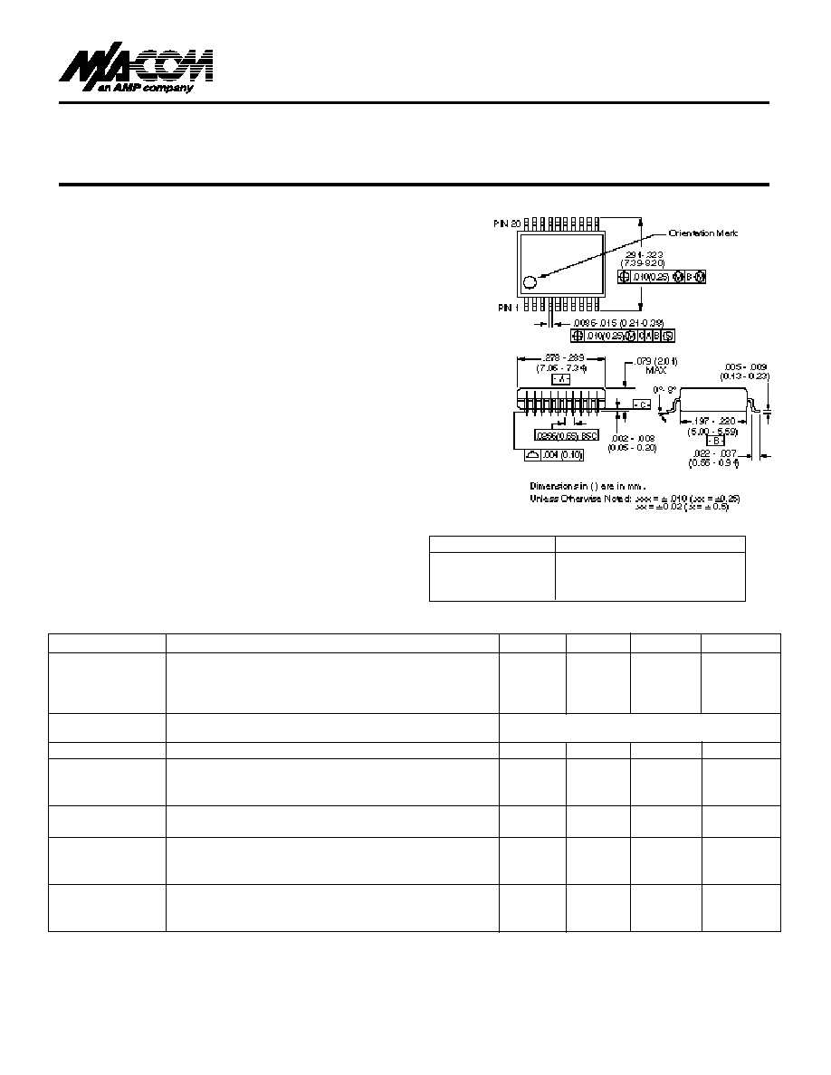
AT-260 PIN
SSOP 20-Lead
AT-260TR
Forward Tape & Reel
*
AT-260RTR
Reverse Tape & Ree
l*
Parameter
Test Conditions
1
Unit
Min.
Typ.
Max
Reference
DC ≠ 0.1 GHz
dB
1.6
1.8
Insertion Loss
DC ≠ 0.5 GHz
dB
1.7
1.9
DC ≠ 1.0 GHz
dB
1.9
2.2
DC ≠ 2.0 GHz
dB
2.2
2.5
Attenuation
DC ≠ 1.0 GHz ± (0.20 dB + 3% of Atten. Setting in dB) dB
Accuracy
2
DC ≠ 2.0 GHz ± (0.30 dB + 3% of Atten.Setting in dB) dB
VSWR
(any state)
1.5:1
Trise, Tfall
10% to 90% RF, 90% to 10% RF
nS
8
Ton, Toff
50% Control to 90% RF, 50% Control to 10% RF
nS
15
Transients
In Band
mV
2
One dB
Input Power
0.05 GHz
dBm
20
Compression
Input Power
0.5-2.0 GHz
dBm
27
IP2
Measured Relative
0.05 GHz
dBm
45
to Input Power
0.5-2.0 GHz
dBm
60
(for two-tone input power up to +5 dBm)
IP3
Measured Relative
0.05 GHz
dBm
34
to Input Power
0.5-2.0 GHz
dBm
50
(for two-tone input power up to +5 dBm)
F e a t u r e s
Attenuation: 1-dB Steps to 31 dB
Te m p e r a t u re Stability: ± 0.15 dB from -40∞C
to +85∞C Ty p i c a l
Ultra Low DC Power Consumption
Low Intermodulation Products: IP3 = 50 dBm
Low Cost SSOP 20 Plastic Package
Tape and Reel Packaging Av a i l a b l e
D e s c r i p t i o n
M/A-COM's AT-260 is a 5-bit, 1-dB step GaAs MMIC digi-
tal attenuator in a low cost SSOP-20 surface mount plastic
package. The AT-260 is ideally suited for use where high
accuracy, fast switching, very low power consumption and
low intermodulation products are re q u i red at a low cost.
Typical applications include radio and cellular equipment,
w i reless LANS, GPS equipment and other Gain/Level
C o n t rol circ u i t s .
The AT-260 is fabricated with a monolithic GaAs MMIC
using a mature 1-micron process. The process features full
chip passivation for increased perf o rmance and re l i a b i l i t y .
Digital Attenuator, 31 dB, 5-Bit
DC ≠ 2 GHz
AT-260
S S O P - 2 0
1. All measurements at 1 GHz in a 50
system, unless otherwise specified.
2.Attenuation accuracy specifications apply with negative bias control and low inductance grounding.
q
q
q
q
q
q
O rdering Info r m a t i o n
Electrical Specifications, T
A
= 25∞C
*
If specific reel size is requIred, consult factory for part number
assignment.
V 2.00

V 2.00
Parameter
Absolute Maximum
Max. Input Power
0.05 GHz
+27 dBm
0.5≠2.0 GHz
+34 dBm
Control Voltage
+5V, ≠8.5V
Operating Temperature
≠40∞C to +85∞C
Storage Temperature
≠65∞C to +150∞C
Control Inputs
VC5 VC4 VC4 VC3 VC3 VC2 VC2 VC1 VC1 Attenuation
(dB)
1
1
0
1
0
1
0
1
0
Reference
0
1
0
1
0
1
0
1
0
1 dB
1
0
1
1
0
1
0
1
0
2 dB
1
1
0
0
1
1
0
1
0
4 dB
1
1
0
1
0
0
1
1
0
8 dB
1
1
0
1
0
1
0
0
1
16 dB
0
0
1
0
1
0
1
0
1
31 dB
Absolute Maximum Ratings
1
Functional Sch e m a t i c
Pin No.
Description
Pin No.
Description
1
VC1
11
RF1
2
VC1
12
GND
3
VC2
13
GND
4
VC2
14
GND
5
VC3
15
GND
6
VC3
16
GND
7
VC4
17
GND
8
VC4
18
GND
9
NC
19
GND
10
VC5
20
RF2
1. Operation of this device above any one of these parameters may
cause permanent damage.
Typical Performance
Pin Configuration
Truth Ta bl e
0 = V
IN
Low = 0 V = 0 to -0.2 V @ 20 µA maximum
1 = V
IN
High = -5 V @ 20 µA typical to -8 V @ 200 µA maximum