Digital Attenuator, 4 Bit, Single Control, 30 dB, 0.5 - 2.0 GHz
AT-264
M/A-COM Division of AMP Incorporated
3
North America: Tel. (800) 366-2266, Fax (800) 618-8883
3
Asia/Pacific: Tel.+85 2 2111 8088, Fax +85 2 2111 8087
3
Europe: Tel. +44 (1344) 869 595, Fax+44 (1344) 300 020
www.macom.com
AMP and Connecting at a Higher Level are trademarks.
Specifications subject to change without notice.
V3.00
Features
∑
Single Control CMOS logic for each bit
∑
Attenuation 2 dB steps to 30 dB
∑
Low DC Power Consumtion: 50 uW
∑
Low Cost Plastic TSSOP-16 Package
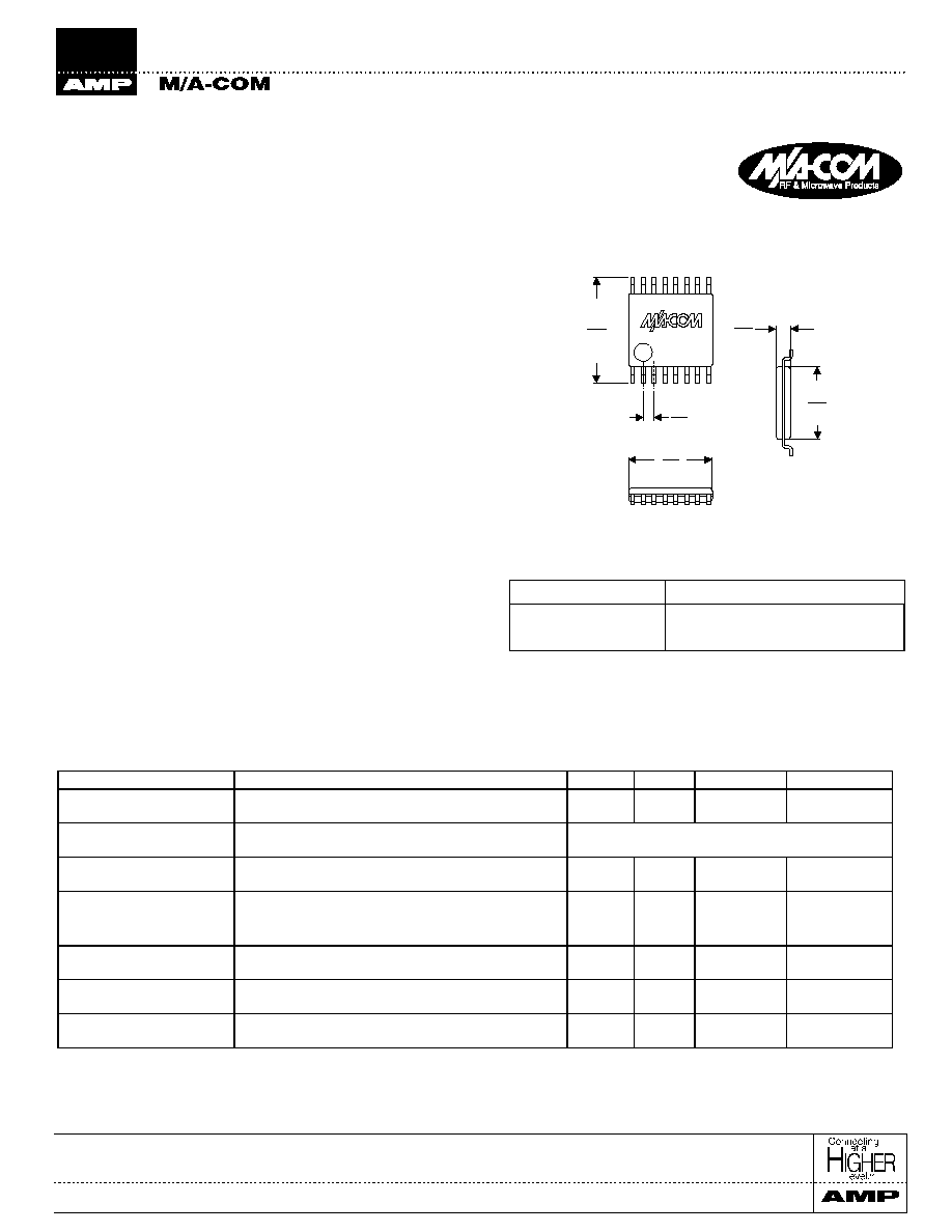
TSSOP-16
1
Electrical Specifications: T
A
= +25∞C
1
Digital Attenuator, 4 Bit, Single Control
30 dB, 0.5 - 2.0 GHz
AT-264
Description
The M/A-COM AT-264 is a 4 bit, 2 dB step GaAs MMIC
digital attenuator in a low cost TSSOP-16 surface mount plastic
package. The AT-264 is ideally suited for use where high
accuracy, very low power consumption and low intermodula-
tion products are required. Typical applications include radio,
cellular, wireless LANs, GPS equipment and other gain/level
control circuits.
The AT-264 is fabricated using a mature 1 micron GaAs
MESFET process. The process features full chip passivation
for increased performance and reliability.
Ordering Information
Part Number
Package
AT-264
TSSOP 16-Lead Plastic
AT-264TR
Tape and Reel
1
1. Refer to Application Note M513 for reel size information.
1.
All measurements at 900 MHz in a 50
system unless otherwise specified. Loss varies at 0.003 dB/∞C.
2.
For two-tone Input Power up to +5 dBm.
1. Dimensions are in inches/mm.
.03
03
0,9
0,8
.17
.16
4,0
4,2
25
24
6,0
6,2
.025
0,6
20
19
5,1
4,0
PN 16
PN 1
Parameter
Test Conditions
Units
Min.
Typ.
Max.
Reference Insertion Loss
0.5 - 1.0 GHz
dB
1.6
1.8
0.5 - 2.0 GHz
dB
1.8
2.0
Attenuation Accuracy
0.5 - 1.0 GHz
±(0.15 dB + 5% of Attenuation setting in dB) dB
0.5 - 2.0 GHz
±(0.3 dB + 5% of Attenuation setting in dB) dB
VSWR
1.0 - 1.5 GHz
1.5:1
0.5 - 2.0 GHz
1.9:1
T
rise
, T
fall
T
on
, T
off
Transients
10% to 90% RF, 90% to 10% RF
50% Control to 90% RF, 50% Control to 10% RF
in Band
µ
S
µ
S
mV
3
3
75
1 dB Compression
Input Power 0.5 GHz
Input Power 0.9 GHz
dBm
dBm
25
25
IP
2
Measured Relative to 0.5 GHz
Input Power
2
0.5 - 2.0 GHz
dBm
dBm
65
71
IP
3
Measured Relative to 0.5 GHz
Input Power
2
0.5 - 2.0 GHz
dBm
dBm
43
47
Digital Attenuator, 4 Bit, Single Control, 30 dB, 0.5 - 2.0 GHz
AT-264
M/A-COM Division of AMP Incorporated
3
North America: Tel. (800) 366-2266, Fax (800) 618-8883
3
Asia/Pacific: Tel.+85 2 2111 8088, Fax +85 2 2111 8087
3
Europe: Tel. +44 (1344) 869 595, Fax+44 (1344) 300 020
www.macom.com
AMP and Connecting at a Higher Level are trademarks.
Specifications subject to change without notice.
V3.00
-1 .5
-1
-0 .5
0
0 .5
1
1 .5
0 .5
1
1 .5
2
2 .5
3
F R E Q U E N C Y (G H z )
DEVIATION FROM NOMINAL
ATTENUATION (dB)
3 0 d B A T T E N
4 d B
2 d B A T T E N
8 d B A T T E N
1 6 d B A T T E N
-3 2
-3 0
-2 8
-2 6
-2 4
-2 2
-2 0
-1 8
-1 6
-1 4
-1 2
-1 0
-8
-6
-4
-2
0
0 .5
1
1 .5
2
2 .5
3
F R E Q U E N C Y (G H z )
ATTENUATION (dB)
1
1 .2
1 .4
1 .6
1 .8
2
2 .2
2 .4
2 .6
2 .8
0 .5
1
1 .5
2
2 .5
3
F R E Q U E N C Y (G H z )
VSWR
1 6 , 3 0 d B A T T E N
2 d B A T T E N
IL
0
0 .5
1
1 .5
2
2 .5
0 .5
1
1 .5
2
2 .5
3
F R E Q U E N C Y (G H z )
INSERTION LOSS (dB)
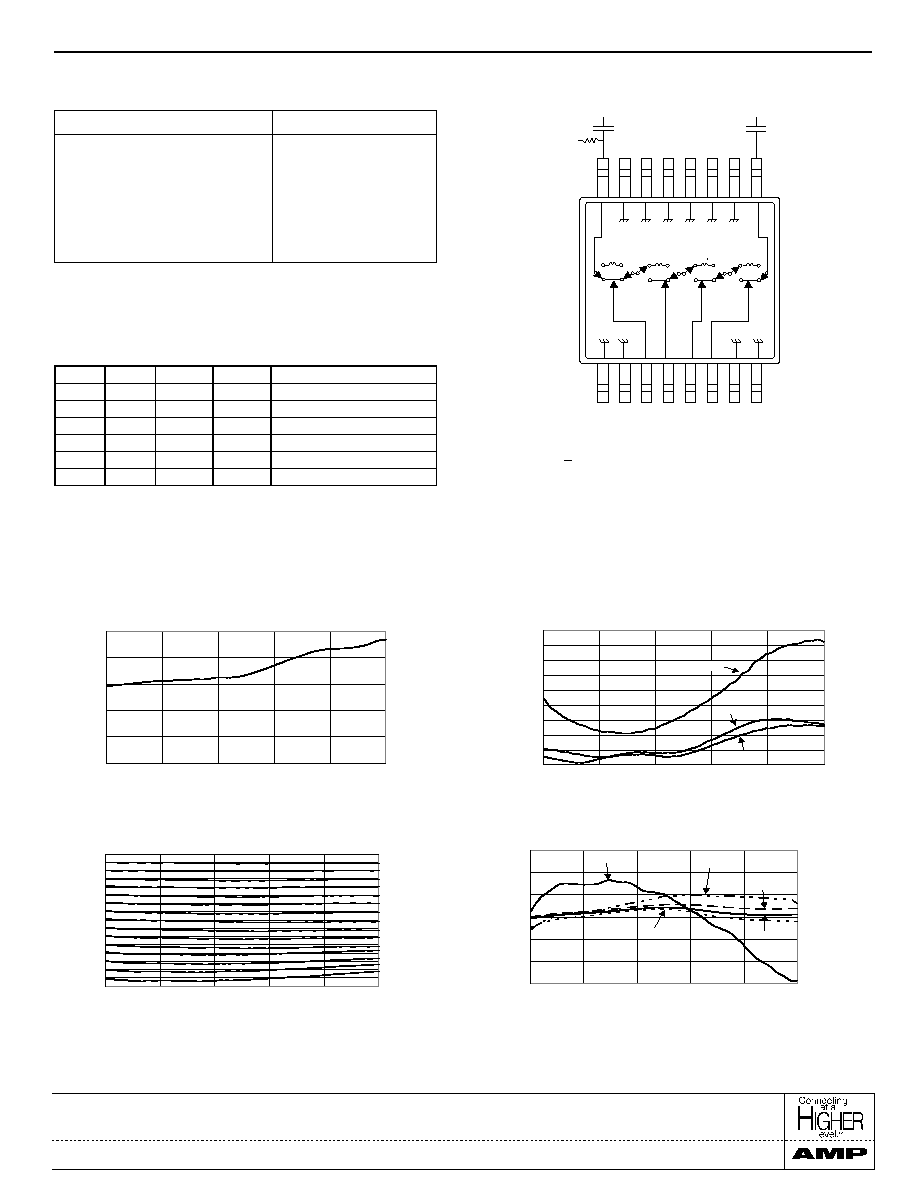
Typical Performance Curves
Attenuation Accuracy vs. Frequency
Functional Schematic
1, 2
Parameter
Absolute Maximum
Input Power
50 MHz
500 - 2000 MHz
+27 dBm
+34 dBm
Control Voltage
+8.5V, -0.5V
Operating Temperature
-40∞C to +85∞C
Storage Temperature
-65∞C to +150∞C
Absolute Maximum Ratings
1
1.
Exceeding any one or a combination of these limits may cause
permanent damage.
1.
Blocking Caps are required on all RF ports, 39 pF used for data
measurements.
2.
Vs = +5+
0.2Vdc can be applied at RF1 or RF2 using a 10K or
greater pull-up resistor.
Insertion Loss vs. Frequency
Attenuation vs. Frequency
VSWR vs. Frequency
GND GND VC1 VC2 VC3 VC4 GND GND
RF1 GND GND GND GND GND
GND RF2
PIN 16
PIN 1
16
8
4
2
Vs
VC1
VC2
VC3
VC4
Attenuation (dB)
1
1
1
1
Reference I.L.
1
1
1
0
2
1
1
0
1
4
1
0
1
1
8
0
1
1
1
16
0
0
0
0
30
Logic 0=0±0.2V
Logic 1 = +5v @ 30 µA max. current total.
Truth Table