Digital Attenuator, 1 Bit, 10 dB Step, DC - 2.0 GHz
AT-266
M/A-COM Division of AMP Incorporated
3
North America: Tel. (800) 366-2266, Fax (800) 618-8883
3
Asia/Pacific: Tel.+85 2 2111 8088, Fax +85 2 2111 8087
3
Europe: Tel. +44 (1344) 869 595, Fax+44 (1344) 300 020
www.macom.com
AMP and Connecting at a Higher Level are trademarks.
Specifications subject to change without notice.
V2.00
Digital Attenuator, 1 Bit, 10 dB Step
DC - 2.0 GHz
AT-266
Features
∑
Single 10 dB Step
∑
Low Loss 0.3dB Typ. @ 900 MHz
∑
Low Cost Plastic SOT25 Package
Description
M/A-COM's AT-266 is a 1 bit, 10 dB step GaAs MMIC Digital
Attenuator in a low cost SOT-25 surface mount plastic package.
The AT-266 is ideally suited for use where high accuracy, very
low power consumption and low intermodulation products are
required. Typical applications include radio, wireless LANs,
GPS equipment and other gain/level control circuits.
The AT-266 is a GaAs MMIC using a mature 1 micron process.
The process features full chip passivation for increased perfor-
mance and reliability.
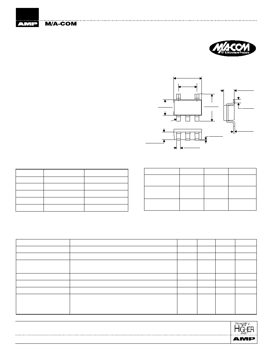
SOT-25 Plastic Package
Pin 1
.114
±
.008
2,9
±
0,2
.075
±
.008
1,90
±
0,2
.063
±
.004
1,6
±
0,1
.110
±
.008
2,80
±
0,2
+ .004
- .007
+ 0,1
- 0,18
.031
0,80
+ .004
- .002
+ 0,1
- 0,05
.016
0,40
.002
±
.002
0,05
±
0,05
+ .004
- .002
+ 0,1
- 0,05
.006
0,15
+ .008
- .004
+ 0,2
- 0,1
.043
1,10
.008 MIN
0,20 MIN
Truth Table
MODE (Control)
V1
V2
Atten.
Postive
1
0 ± 0.2V
+3 to +8V
+3 to +8V
0 ± 0.2V
10 dB
IL
Postive / Negative
1,2
-V
C
± 0.2 V
+ V
C
+V
C
-V
C
± 0.2V
10 dB
IL
Negative
3
0 ± 0.2V
-3V to -8V
-3V to -8V
0 ± 0.2V
IL
10 dB
1. External DC blocking capactors are required as noted
1
2. | -V
C
| + V
C
8 V.
3. If negative control is used, DC blocking capacitors are not
required on RF Ports.
Pin Configuration
PIN No.
Function
Description
1
RF1
1
RF In/Out
2
GND
1
RF Ground
3
RF2
1
RF In/Out
4
V1
Control Voltage
5
V2
Control Voltage
Electrical Specifications T
A
= 25∞C
1
Parameter
Test Conditions
Units
Min.
Typ.
Max.
Insertion Loss
0 - 1 GHz
dB
0.3
0.45
Insertion Loss
1 - 2 GHz
dB
0.5
0.7
Attenuation
0 - 1 GHz
dB
10
±0.4
1 - 2 GHz
dB
10
±0.5
VSWR
0 - 2 GHz
1.4:1
1.5:1
IP
3
2 Tone @ 0 dBm, 5 MHz spacing
dBm
42
50
P
1dB
1 GHz
dBm
23
28
Trise, Tfall
10% to 90% RF, 90% to 10% RF
ns
5
20
Ton, Toff
50% Control to 90% RF, 50% Control to 10% RF
ns
10
25
Transients
In Band
mV
6
10
1. Series Capacitors on PINs1, 3 and 5, Shunt Capacitor on PIN 2
are required for Postive Control. 39pF capacitors used for pos-
tive control performance curves.
1. All measurements at 1.0 GHz, -3 Volts control unless otherwise specified.
Digital Attenuator, 1 Bit, 10 dB Step, DC - 2.0 GHz
AT-266
M/A-COM Division of AMP Incorporated
3
North America: Tel. (800) 366-2266, Fax (800) 618-8883
3
Asia/Pacific: Tel.+85 2 2111 8088, Fax +85 2 2111 8087
3
Europe: Tel. +44 (1344) 869 595, Fax+44 (1344) 300 020
www.macom.com
AMP and Connecting at a Higher Level are trademarks.
Specifications subject to change without notice.
V2.00
9
9.2
9.4
9.6
9.8
10
10.2
10.4
10.6
10.8
11
0
0.5
1
1.5
2
2.5
3
FREGUENCY (GHz)
INSERTION LOSS (dB)
+25∞C
-40∞C
+85∞C
0
0.1
0.2
0.3
0.4
0.5
0.6
0.7
0.8
0.9
1
0
0.5
1
1.5
2
2.5
3
FREGUENCY (GHz)
INSERTION LOSS (dB)
+25∞C
-40∞C
+85∞C
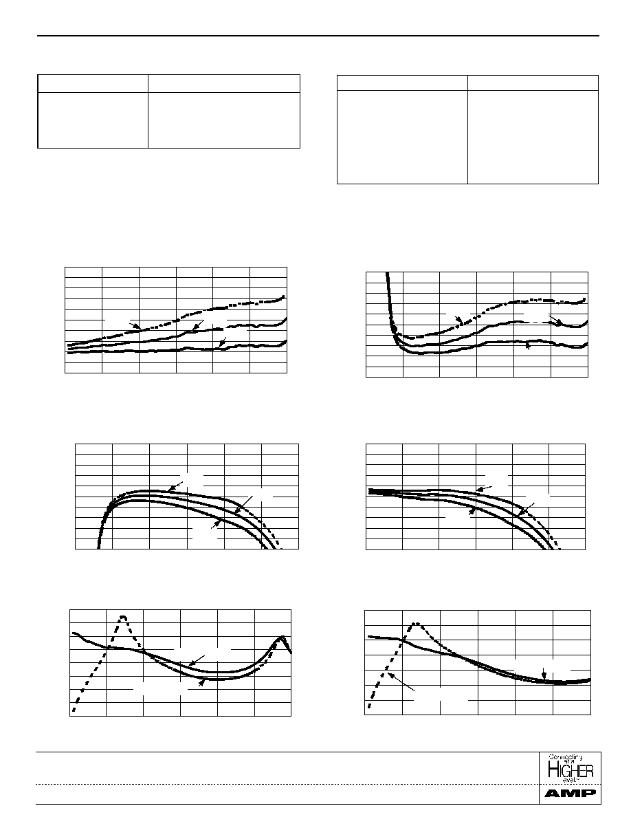
Insertion Loss vs. Frequency Over
Temperature (Negative Control)
0
0.1
0.2
0.3
0.4
0.5
0.6
0.7
0.8
0.9
1
0
0.5
1
1.5
2
2.5
3
FREGUENCY (GHz)
INSERTION LOSS (dB)
+25∞C
-40∞C
+85∞C
Insertion Loss vs. Frequency Over
Temperature (Postive Control)
9
9.2
9.4
9.6
9.8
10
10.2
10.4
10.6
10.8
11
0
0.5
1
1.5
2
2.5
3
FREGUENCY (GHz)
INSERTION LOSS (dB)
+25∞C
-40∞C
+85∞C
Relative Attenuation vs. Frequency Over
Temperature (Posative Control)
Relative Attenuation vs. Frequency Over
Temperature (Negative Control)
0
5
10
15
20
25
30
35
0
0.5
1
1.5
2
2.5
3
FREQUENCY (GHz)
RETURNLOSS (dB)
Positive Control
Negative Control
0
5
10
15
20
25
30
35
40
0
0.5
1
1.5
2
2.5
3
FREQUENCY (GHz)
RETURNLOSS (dB)
Positive Control
Negative Control
Return Loss vs. Frequency
(Reference State)
Return Loss vs. Frequency
(10 dB State)
Typical Performance Curves
Absolute Maximum Ratings
1
Parameter
Absolute Maximum
Max. Input Power
50 MHz
+27 dBm
500 - 2000 MHz
+34 dBm
Control Voltage
+5V, -8.5V
Operating Temperature
-40∞C to +85∞C
Storage Temperature
-65∞C to +150∞C
1. Operation of this device above any one of these parameters may
cause permanent damage.
Ordering Information
Part Number
Package
AT-266
SOT-25 Plastic Package
AT-266TR
Forward Tape and Reel
1
AT-266RTR
Reverse Tape and Reel
1
1. Refer to Application Note M513 for reel size information.