Voltage Variable Attenuator,
900 - 2500 MHz
AT65
-
0008
SO-8
V 5.00
Electrical Specifications: T
A
= 25∞C, Frequency: ± 5% Bandwidth,
900-2500 MHz
Parameter
Test Conditions
Units
Min.
Typ.
Max.
Insertion Loss
2V
dB
--
1.2
1.5
VSWR
0 to 10 dB
Ratio
--
1.6:1
2.0:1
VSWR
10 to 20 dB
Ratio
--
1.8:1
2.0:1
Attenuation
0V
dB
25
28
--
Attenuation Flatness
vs Frequency
to 10 dB
to 20 dB
to 30 dB
dB
dB
dB
--
--
--
0.1
0.15
1.2
0.2
0.3
1.5
Switching Speed
50% Control to 90%/10% RF
µSec
--
2
5
Linear Operation
0 to 20 dB
dBm
--
+17
+15
Input IP
3
Two-tone inputs to +5 dBm
dBm
+40
--
--
Features
n
High Third Order Intercept Point
n
Surface Mount Package
n
25 dB Dynamic Range
n
±5% Operating Bandwidth
n
PIN Diode Based
n
Single Control Voltage
Description
M/A-COM's AT65-0008 is a PIN diode based voltage
variable attenuator. It is packaged in an 8 lead small outline
narrow body plastic, surface mount package. The attenuator
has linear operating power and intercept point levels higher
than GaAs FET MMIC based voltage variable attenuators.
The VVA is suited for use where low distortion and high
linear operating power are required. The device operating
frequency is selected in the 900 to 2500 MHz frequency
band by defining the length of the T/4 (a quarter wave
transmission line at the operating frequency) connected to
pins 5 and 6.
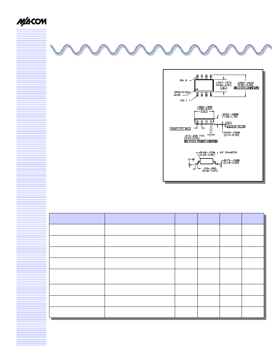
Package outline conforms to JEDEC standard MS-012AA.
Voltage Variable Attenuator, 900 - 2500 MHz
AT65-0008
Specifications subject to change without notice.
n
North America: Tel. (800) 366-2266
n
Asia/Pacific: Tel.+81-44-844-8296, Fax +81-44-844-8298
n
Europe: Tel. +44 (1344) 869 595, Fax+44 (1344) 300 020
Visit www.macom.com for additional data sheets and product information.
V 5.00
2
Pin Configuration
Pin No.
Function
Pin No.
Function
1
RF Input
5
Transmission
Line Out
2
GND
6
Transmission
Line In
3
Bias Input
7
GND
4
GND
8
RF Output
Absolute Maximum Ratings
Parameter
Absolute Maximum
Max. Input Power
+27 dBm
Operating Voltage
+ 10 Volts
Operating Temperature
-40∞C to +85∞C
Storage Temperature
-65∞C to +125∞C
Typical Performance Curves
Attenuation Flatness, 3 dB
IP3 vs. Attenuation
-0.4
-0.2
0
0.2
0.4
Fc - 5%
Fc - 3%
Fc
Fc + 3%
Fc + 5%
Frequency (GHz)
Deviation from Nom. Atten. (dB)
30
35
40
45
50
55
0 dB
3 dB
6 dB
10 dB
15 dB
20 dB
22 dB
Attenuation
IP3 (dB)
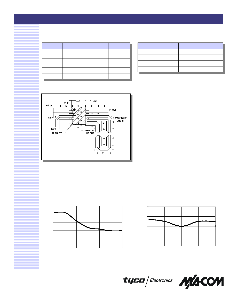
Recommended PCB Configuration
1. Circuit Material - GETEK, .014 Thick
2. 90∞ of length consists of printed transmission line plus
effective length of internal circuitry and lead length.
Voltage Variable Attenuator, 900 - 2500 MHz
AT65-0008
Specifications subject to change without notice.
n
North America: Tel. (800) 366-2266
n
Asia/Pacific: Tel.+81-44-844-8296, Fax +81-44-844-8298
n
Europe: Tel. +44 (1344) 869 595, Fax+44 (1344) 300 020
Visit www.macom.com for additional data sheets and product information.
V 5.00
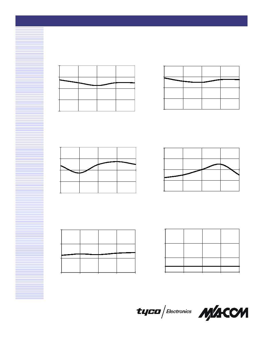
Typical Performance Curves
Attenuation Flatness, 10 dB
Attenuation Flatness, 6 dB
Attenuation Flatness, 15 dB
3
Attenuation Flatness, 20 dB
RF Input VSWR vs. Freq, Ins. Loss
RF Input VSWR vs. Freq, 3 dB
-0.4
-0.2
0
0.2
0.4
Fc - 5%
Fc - 3%
Fc
Fc + 3%
Fc + 5%
Frequency (GHz)
Deviation from Nom. Atten. (dB)
-0.4
-0.2
0
0.2
0.4
Fc - 5%
Fc - 3%
Fc
Fc + 3%
Fc + 5%
Frequency (GHz)
Deviation from Nom. Atten. (dB)
-0.4
-0.2
0
0.2
0.4
Fc - 5%
Fc - 3%
Fc
Fc + 3%
Fc + 5%
Frequency (GHz)
Deviation from Nom. Atten. (dB)
-0.4
-0.2
0
0.2
0.4
Fc - 5%
Fc - 3%
Fc
Fc + 3%
Fc + 5%
Frequency (GHz)
Deviation from Nom. Atten. (dB)
1.4
1.6
1.8
2
Fc - 5%
Fc - 3%
Fc
Fc + 3%
Fc + 5%
Frequency (GHz)
VSWR
1.4
1.6
1.8
2
Fc - 5%
Fc - 3%
Fc
Fc + 3%
Fc + 5%
Frequency (GHz)
VSWR
Voltage Variable Attenuator, 900 - 2500 MHz
AT65-0008
Specifications subject to change without notice.
n
North America: Tel. (800) 366-2266
n
Asia/Pacific: Tel.+81-44-844-8296, Fax +81-44-844-8298
n
Europe: Tel. +44 (1344) 869 595, Fax+44 (1344) 300 020
Visit www.macom.com for additional data sheets and product information.
V 5.00
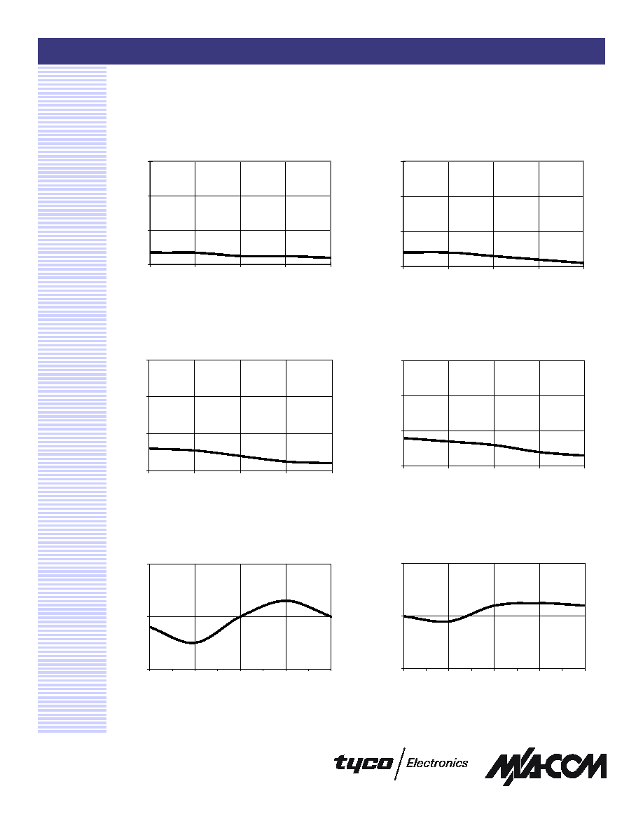
Typical Performance Curves
RF Input VSWR vs. Freq, 10 dB
RF Input VSWR vs. Freq, 6 dB
RF Input VSWR vs. Freq, 15 dB
4
RF Input VSWR vs. Freq, 20 dB
Typical Insertion Loss @ +25∞C
Typical Insertion Loss @ -40∞C
1.4
1.6
1.8
2
Fc - 5%
Fc - 3%
Fc
Fc + 3%
Fc + 5%
Frequency (GHz)
VSWR
1.4
1.6
1.8
2
Fc - 5%
Fc - 3%
Fc
Fc + 3%
Fc + 5%
Frequency (GHz)
VSWR
1.4
1.6
1.8
2
1.52
1.51
1.48
1.45
1.44
Frequency (GHz)
VSWR
1.4
1.6
1.8
2
Fc - 5%
Fc - 3%
Fc
Fc + 3%
Fc + 5%
Frequency (GHz)
VSWR
0
1
2
Fc - 5%
Fc - 3%
Fc
Fc + 3%
Fc + 5%
Frequency (GHz)
Loss (dB)
0
1
2
Fc - 5%
Fc - 3%
Fc
Fc + 3%
Fc + 5%
Frequency (GHz)
Loss (dB)
Voltage Variable Attenuator, 900 - 2500 MHz
AT65-0008
Specifications subject to change without notice.
n
North America: Tel. (800) 366-2266
n
Asia/Pacific: Tel.+81-44-844-8296, Fax +81-44-844-8298
n
Europe: Tel. +44 (1344) 869 595, Fax+44 (1344) 300 020
Visit www.macom.com for additional data sheets and product information.
V 5.00
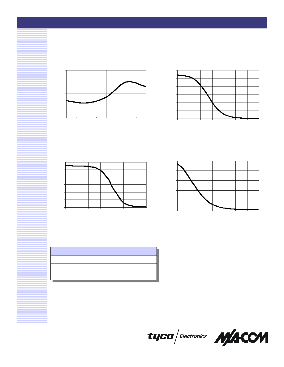
Typical Performance Curves
Attenuation vs. Voltage at Fc +25∞C
Typical Insertion Loss @ +85∞C
Attenuation vs. Voltage at Fc ≠40∞C
5
Attenuation vs. Voltage at Fc +85∞C
Ordering Information
Part Number
Package
AT65-0008
Bulk Packaging
AT65-0008TR
Tape and Reel (1K Reel)
AT65-0008-TB
Units Mounted on Test Board
0
1
2
Fc - 5%
Fc - 3%
Fc
Fc + 3%
Fc + 5%
Frequency (GHz)
Loss (dB)
0
5
10
15
20
25
30
0.50
0.70
0.90
1.10
1.30
1.50
1.70
1.90
Voltage
Attenuation (dB)
0
5
10
15
20
25
30
0.50
0.70
0.90
1.10
1.30
1.50
1.70
1.90
Voltage
Attenuation (dB)
0
5
10
15
20
25
0.50
0.70
0.90
1.10
1.30
1.50
1.70
1.90
Voltage
Attenuation (dB)