Digital Attenuator, 15 dB, 4-Bit,
TTL Driver, DC - 3.0 GHz
AT65
-
0213
SOW-16
V 5.00
Electrical Specifications: T
A
= 25∞C
Features
n
Attenuation: 1.0dB Steps to 15dB
n
Low DC Power Consumption
n
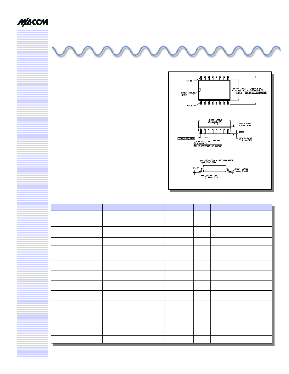
Plastic SOIC, Wide Body, SMT Package
n
Integral TTL Driver
n
50 ohm Impedance
n
Temperature Stability: ±0.18 dB from -55∞C to +85∞C
Typ.
n
Tape and Reel Packaging Available
Description
M/A-COM's AT65-0213 is a GaAs FET 4-bit digital
attenuator with a 1.0dB minimum step size and a 15 dB
total attenuation range. This device is in a SOIC-16 plastic
surface mount package. The AT65-0213 is ideally suited for
use where accuracy, fast speed, very low power
consumption and low costs are required. Typical
applications include dynamic range setting in precision
receiver circuits and other gain/leveling control circuits.
Package outline conforms to JEDEC standard MS-013AA.
Parameter
Test Conditions
Frequency
Units
Min
Typical
Max
Insertion Loss
--
DC - 0.5 GHz
DC - 2.0 GHz
DC - 3.0 GHz
dB
dB
dB
--
--
--
--
--
--
2.2
2.5
2.8
Attenuation Accuracy
Any Bit or Combination of Bits
DC - 2.0 GHz
DC - 3.0 GHz
dB
dB
- (0.2 +2% of attenuation setting)
+ (0.4 +10% of attenuation setting)
VSWR
Full Range
DC - 2.0 GHz
Ratio
--
--
2.0:1
Trise, Tfall
Ton, Toff
Transients
10% to 90%
50% Cntl to 90%/10% RF
In-Band
nS
nS
mV
--
--
--
9
40
30
--
--
--
1 dB Compression
Input Power
Input Power
0.05 GHz
0.5 - 3.0 GHz
dBm
dBm
--
--
+22
+28
--
--
Input IP
3
Two-tone inputs up to +5 dBm
0.05 GHz
0.5 - 3.0 GHz
dBm
dBm
--
--
+40
+50
--
--
Input IP
2
Two-tone inputs up to +5 dBm
0.05 GHz
0.5 - 3.0 GHz
dBm
dBm
--
--
+45
+68
--
--
Vcc
-Vee
--
--
--
--
V
V
4.5
-8.0
5.0
-5.0
5.5
-4.75
Vctl
Vctl
Logic (0) TTL
Logic (1) TTL
--
--
V
V
0.0
2.0
---
--
0.8
5.0
Input Leakage Current (Low)
Input Lekage Current (High)
0 to 0.8 V
2.0 to 5.0 V
--
--
µA
µA
--
--
--
--
20
20
Icc
Vcc = 4.5 to 5.5V
Vctl = 0 to 0.8V,
or V
CC
-2.1 V to V
CC
--
mA
--
--
4.0
-Iee
Vee = -5.0 to -8.0 V
--
mA
--
--
-1
Digital Attenuator, 15 dB, 4-Bit, TTL Driver, DC - 3.0 GHz
AT65-0213
Specifications subject to change without notice.
n
North America: Tel. (800) 366-2266
n
Asia/Pacific: Tel.+81-44-844-8296, Fax +81-44-844-8298
n
Europe: Tel. +44 (1344) 869 595, Fax+44 (1344) 300 020
Visit www.macom.com for additional data sheets and product information.
V 5.00
2
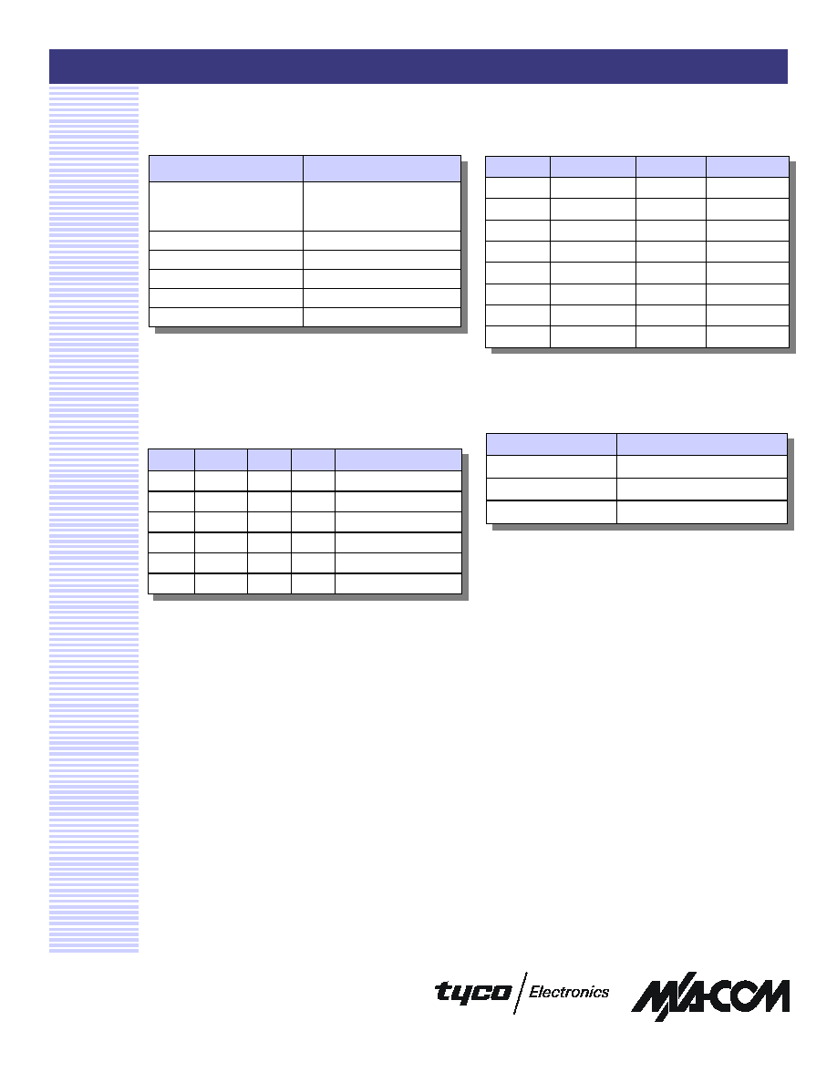
Pin Configuration
Pin #
Function
Pin #
Function
1
GND
9
C2
2
RF1
10
C1
3
GND
11
GND
4
N/C
12
GND
5
Vee
3
13
Vee
3
6
Vcc
14
GND
7
C4
15
RF2
8
C3
16
GND
Truth Table
C1
C2
C3
C4
Attenuation
0
0
0
0
Loss, Reference
1
0
0
0
1.0 dB
0
1
0
0
2.0 dB
0
0
1
0
4.0 dB
0
0
0
1
8.0 dB
1
1
1
1
15.0 dB
0 = TTL Low; 1 = TTL High
Absolute Maximum Ratings
1
Parameter
Absolute Maximum
Max. Input Power
0.05 GHz
0.5 - 3.0 GHz
+27 dBm
+34 dBm
+Vcc
+5.5V
-Vee
-8.5V
Control Voltage
2
-0.5 to Vcc + 0.5V
Operating Temperature
-40∞C to +85∞C
Storage Temperature
-65∞C to +125∞C
1. Operation of this device above any one of these parameters
may cause perament damage.
2. Standard CMOS TTL interface, latch-up will occur if logic
signal is applied prior to power supply.
3. Either or both pins may be connected to Vee.
Ordering Information
Part Number
Package
AT65-0213
Bulk Packaging
AT65-0213TR
Tape and Reel (1K Reel)
AT65-0213-TB
Units Mounted on Test Board