 | –≠–ª–µ–∫—Ç—Ä–æ–Ω–Ω—ã–π –∫–æ–º–ø–æ–Ω–µ–Ω—Ç: AT90-1106 | –°–∫–∞—á–∞—Ç—å:  PDF PDF  ZIP ZIP |
Digital Attenuator, 50 dB, 6-Bit,
TTL Driver, DC-2.4 GHz
AT90
-
1106
CSP-1
V 5.00
Electrical Specifications
T
A
= +25∞C
Parameter
Test Conditions
Frequency
Units
Min
Typical
Max
Insertion Loss
--
DC - 2.4 GHz
dB
--
5.5
6.0
Attenuation
Accuracy
Individual Bits 1-2-4-8-16-32 dB
Any Combination of Bits
1 to 50 dB
DC - 2.4 GHz
DC - 2.4 GHz
dB
dB
--
--
--
--
±(.3 +5% of atten setting)
±(.5 +8% of atten setting)
VSWR
Full Range
DC - 2.4 GHz
Ratio
--
1.8:1
2:1
Switching Speed
50% Cntl to 90%/10% RF
10% to 90% or 90% to 10%
--
--
nS
nS
--
--
75
20
150
50
1 dB Compression
--
--
50 MHz
0.5 - 2.40 GHz
dBm
dBm
--
--
+21
+29
--
--
Input IP
3
Two-tone inputs up to +5 dBm
50 MHz
0.5-2.4 GHz
dB
dB
--
--
+35
+48
--
--
+Vcc
--
--
V
4.75
5.0
5.25
Logic "0"
Sink Current is 20 µA max.
--
V
0.0
--
0.8
Logic "1"
Source Current is 20 µA max.
--
V
2.0
--
5.0
Icc
Vcc min to max,
Logic "0" or "1"
--
mA
--
6
10
Features
n
Attenuation: 1 dB Steps to 50 dB
n
Single Positive Supply
n
Contains Internal DC to DC Converter
n
Low DC Power Consumption
n
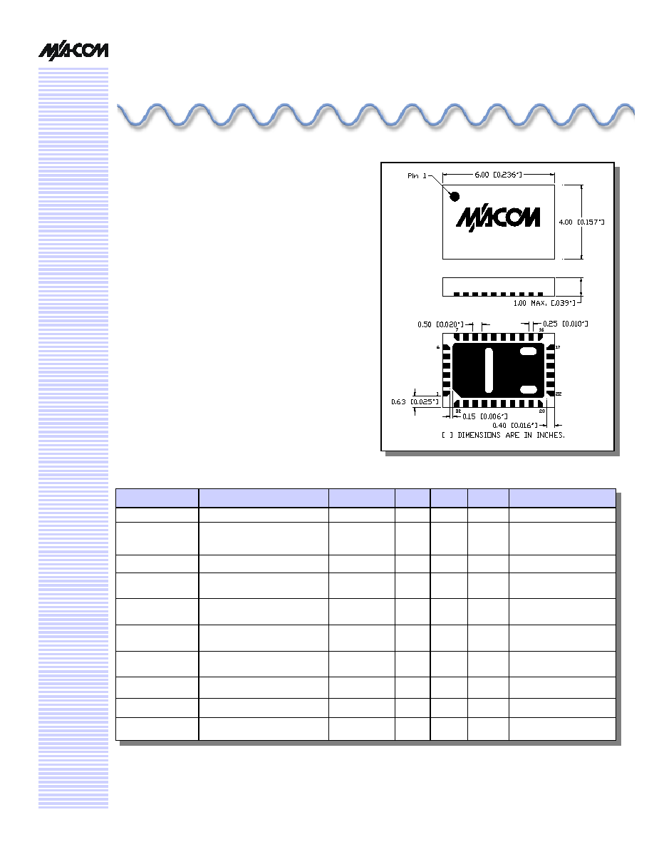
Small Footprint, JEDEC Package
n
Integral TTL Driver
n
50 ohm Impedance
Description
M/A-COM's AT90-1106 is a GaAs FET 6-bit digital
attenuator with integral TTL driver. Step size is 1 dB pro-
viding a 50 dB total attenuation range. This device is in a
FQFP-N plastic surface mount package. The AT90-1106 is
ideally suited for use where accuracy, fast speed, very low
power consumption and low costs are required.
Digital Attenuator, 50 dB, 6-Bit, TTL Driver, DC - 2.4 GHz
AT90-1106
Specifications subject to change without notice.
n
North America: Tel. (800) 366-2266
n
Asia/Pacific: Tel.+81-44-844-8296, Fax +81-44-844-8298
n
Europe: Tel. +44 (1344) 869 595, Fax+44 (1344) 300 020
Visit www.macom.com for additional data sheets and product information.
V 5.00
2
Absolute Maximum Ratings
8
Parameter
Absolute Maximum
Max. Input Power
0.05 GHz
0.5 - 2.4 GHz
+27 dBm
+34 dBm
+Vcc
+5.5V
Logic Voltages
9
-0.5 to +Vcc + 0.5V
Operating Temperature
-40∞C to +85∞C
Storage Temperature
-65∞C to +125∞C
8. Operation of this device above any one of these
parameters may cause permanent damange.
9. Standard CMOS TTL interface, latch-up will occur if logic
signal is applied prior to power supply.
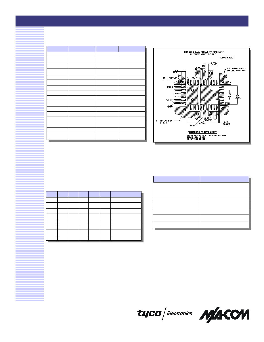
Recommended PCB Layout
7
Truth Table
C32 C16 C8
C4
C2
C1
Attenuation
0
0
0
0
0
0
Loss, Reference
0
0
0
0
0
1
1.0 dB
0
0
0
0
1
0
2.0 dB
0
0
0
1
0
0
4.0 dB
0
0
1
0
0
0
8.0 dB
0
1
0
0
0
0
16.0 dB
1
0
0
0
0
0
32.0 dB
1
1
0
0
1
0
50.0 dB
0 = TTL Low; 1 = TTL High
Pin Configuration
Pin #
Function
Pin #
Function
1
C16
17
NC
2
C8
18
NC
3
C4
19
+Vcc
2
4
C2
20
NC
5
C1
21
Cp
4
6
C32
22
NC
7
GND
23
Cp
4
8
NC
24
NC
9
NC
25
-Vee
3
10
NC
1
26
GND
11
GND
27
RF2
12
RF1
28
GND
13
GND
29
NC
1
14
NC
30
-Vee
3,5
15
NC
31
NC
16
NC
32
+Vcc
2,6
1.
Pins 10 & 29 must be isolated
2.
Pin 19 must be connected to Pin 32
3.
Pin 25 must be connected to Pin 30
4.
.01µF cap must be connected between Pins 21 and 23
5.
-Vee is produced internally and requires a .1µF cap to
GND
6.
+Vcc requires a .1µF cap to GND
7. Application Note C2083 is available on line at
www.macom.com
Digital Attenuator, 50 dB, 6-Bit, TTL Driver, DC - 2.4 GHz
AT90-1106
Specifications subject to change without notice.
n
North America: Tel. (800) 366-2266
n
Asia/Pacific: Tel.+81-44-844-8296, Fax +81-44-844-8298
n
Europe: Tel. +44 (1344) 869 595, Fax+44 (1344) 300 020
Visit www.macom.com for additional data sheets and product information.
V 5.00
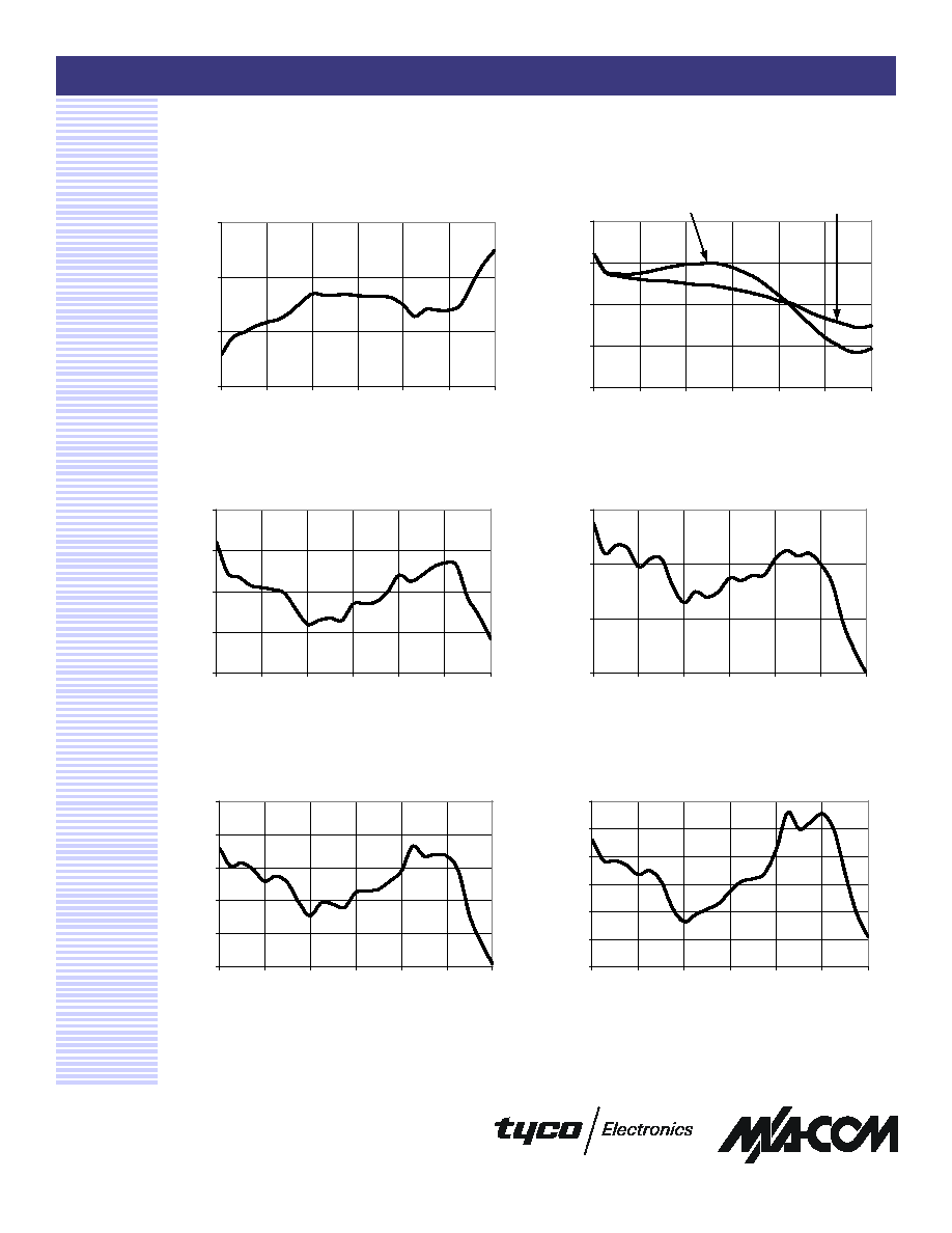
Typical Performance Curves
3
Attenuation Error, 2 dB Bit
Attenuation Error, 1 dB Bit
Attenuation Error, 4 dB Bit
Attenuation Error, 8 dB Bit
-0.2
-0.1
0.0
0.1
0.2
0
400
800
1200
1600
2000
2400
Frequency (MHz)
Attenuation Error (dB)
-0.1
0.0
0.1
0.2
0
400
800
1200
1600
2000
2400
Frequency (MHz)
Attenuation Error (dB)
-0.1
0.0
0.1
0.2
0.3
0.4
0
400
800
1200
1600
2000
2400
Frequency (MHz)
Attenuation Error (dB)
-0.2
-0.1
0.0
0.1
0.2
0.3
0.4
0
400
800
1200
1600
2000
2400
Frequency (MHz)
Attenuation Error (dB)
Insertion Loss
3.0
4.0
5.0
6.0
0
400
800
1200
1600
2000
2400
Frequency (MHz)
Loss (dB)
VSWR @ Insertion Loss
1.0
1.3
1.6
1.9
2.2
0
400
800
1200
1600
2000
2400
Frequency (MHz)
VSWR
Input
Output
Digital Attenuator, 50 dB, 6-Bit, TTL Driver, DC - 2.4 GHz
AT90-1106
Specifications subject to change without notice.
n
North America: Tel. (800) 366-2266
n
Asia/Pacific: Tel.+81-44-844-8296, Fax +81-44-844-8298
n
Europe: Tel. +44 (1344) 869 595, Fax+44 (1344) 300 020
Visit www.macom.com for additional data sheets and product information.
V 5.00
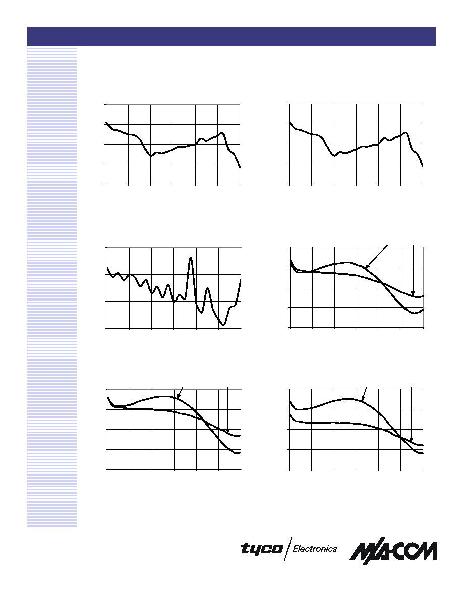
Typical Performance Curves
4
Attenuation Error, 16 dB Bit
Attenuation Error, 32 dB Bit
-0.6
-0.2
0.2
0.6
1.0
0
400
800
1200
1600
2000
2400
Frequency (MHz)
Attenuation Error (dB)
-0.6
-0.2
0.2
0.6
1.0
0
400
800
1200
1600
2000
2400
Frequency (MHz)
Attenuation Error (dB)
Attenuation Error, Max. Attenuation
VSWR, 1 dB Bit
VSWR, 2 dB Bit
-3.5
-1.5
0.5
2.5
0
400
800
1200
1600
2000
2400
Frequency (MHz)
Attenuation Error (dB)
1.0
1.2
1.4
1.6
1.8
0
400
800
1200
1600
2000
2400
Frequency (MHz)
VSWR
Input
Output
1.0
1.2
1.4
1.6
1.8
0
400
800
1200
1600
2000
2400
Frequency (MHz)
VSWR
Input
Output
VSWR, 4 dB Bit
1.0
1.2
1.4
1.6
1.8
0
400
800
1200
1600
2000
2400
Frequency (MHz)
VSWR
Input
Output
Digital Attenuator, 50 dB, 6-Bit, TTL Driver, DC - 2.4 GHz
AT90-1106
Specifications subject to change without notice.
n
North America: Tel. (800) 366-2266
n
Asia/Pacific: Tel.+81-44-844-8296, Fax +81-44-844-8298
n
Europe: Tel. +44 (1344) 869 595, Fax+44 (1344) 300 020
Visit www.macom.com for additional data sheets and product information.
V 5.00
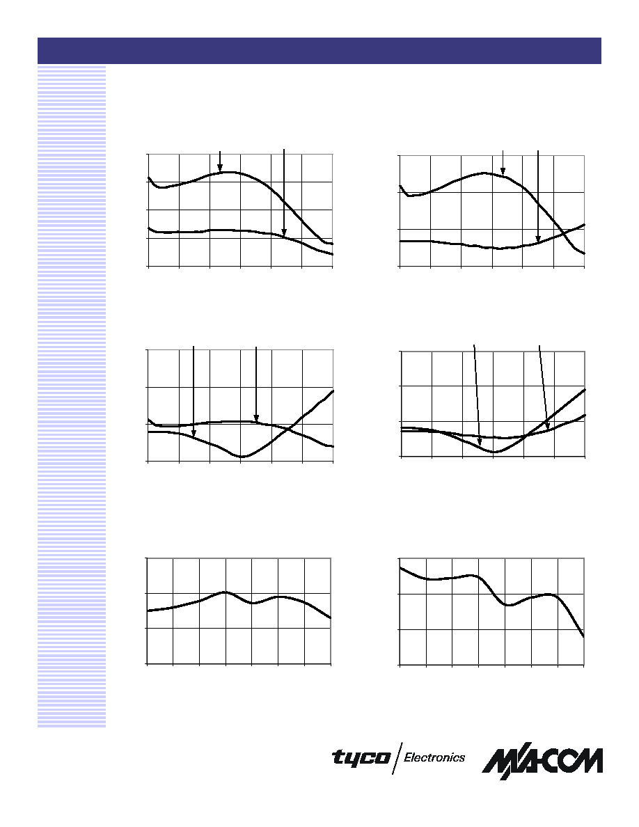
Typical Performance Curves
5
VSWR, 8 dB Bit
1.0
1.2
1.4
1.6
1.8
0
400
800
1200
1600
2000
2400
Frequency (MHz)
VSWR
Input
Output
VSWR, 32 dB Bit
VSWR, 16 dB Bit
VSWR, Maximum Attenuation
Maximum IP3 over Temperature
Range and Attenuation @ 50 MHz
20
30
40
50
Loss
1
2
4
8
16
32
50
Attenuation (dB)
IP3
1.0
1.2
1.4
1.6
0
400
800
1200
1600
2000
2400
Frequency (MHz)
VSWR
Input
Output
1.00
1.20
1.40
1.60
0
400
800
1200
1600
2000
2400
Frequency (MHz)
VSWR
Input
Output
1.0
1.2
1.4
1.6
0
400
800
1200
1600
2000
2400
Frequency (MHz)
VSWR
Input
Output
Maximum IP3 over Temperature
Range and Attenuation @ 950 MHz
20
30
40
50
Loss
1
2
4
8
16
32
50
Attenuation (dB)
IP3
Digital Attenuator, 50 dB, 6-Bit, TTL Driver, DC - 2.4 GHz
AT90-1106
Specifications subject to change without notice.
n
North America: Tel. (800) 366-2266
n
Asia/Pacific: Tel.+81-44-844-8296, Fax +81-44-844-8298
n
Europe: Tel. +44 (1344) 869 595, Fax+44 (1344) 300 020
Visit www.macom.com for additional data sheets and product information.
V 5.00
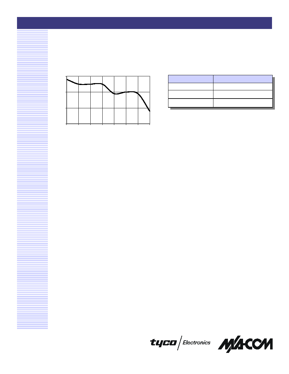
6
Ordering Information
Part Number
Package
AT90-1106
Bulk Packaging
AT90-1106TR
Tape and Reel (1K Reel)
AT90-1106-TB
Units Mounted on Test Board
Typical Performance Curves
Maximum IP3 over Temperature
Range and Attenuation @ 1900 MHz
20
30
40
50
Loss
1
2
4
8
16
32
50
Attenuation (dB)
IP3