Series Number
DN4835
3003 9th Avenue SW
DN6149
PO Box 50
DN8140
Watertown, SD 57201
DN8155
Toll free: 888-978-2638
DN1047
Ph: 605-886-3326
DN1058
Fax: 605-886-8995
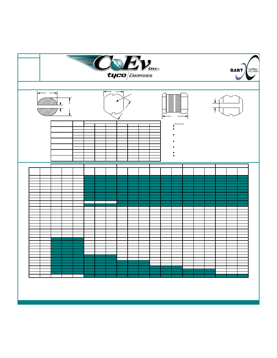
SMD Unshielded Inductor Series; Part Numbering Sequence: ( Series Number ) - ( Suffix Code )(Tolerance), example DQ1260-220M
Bulk Packaging add (-B) to end of Part Numbering Sequence. example DQ1260-22M-B
Series
Maximum Dimensions
Number
Units
D
W
H
Y
A
B
C
inches
0.189"
0.169"
0.138"
0.047"
0.217"
0.047"
0.169"
[ mm ]
[ 4.80 ]
[ 4.30 ]
[ 3.50 ]
[ 1.20 ]
[ 5.50 ]
[ 1.20 ]
[ 4.30 ]
inches
0.240"
0.217"
0.193"
0.051"
0.268"
0.051"
0.217"
[ mm ]
[ 6.10 ]
[ 5.50 ]
[ 4.90 ]
[ 1.30 ]
[ 6.80 ]
[ 1.30 ]
[ 5.50 ]
inches
0.319"
0.287"
0.157"
0.083"
0.346"
0.083"
0.287"
[ mm ]
[ 8.10 ]
[ 7.30 ]
[ 4.00 ]
[ 2.10 ]
[ 8.80 ]
[ 2.10 ]
[ 7.30 ]
inches
0.319"
0.287"
0.217"
0.083"
0.346"
0.083"
0.287"
[ mm ]
[ 8.10 ]
[ 7.30 ]
[ 5.50 ]
[ 2.10 ]
[ 8.80 ]
[ 2.10 ]
[ 7.30 ]
inches
0.406"
0.366"
0.185"
0.114"
0.433"
0.114"
0.366"
[ mm ]
[ 10.30 ]
[ 9.30 ]
[ 4.70 ]
[ 2.90 ]
[ 11.00 ]
[ 2.90 ]
[ 9.30 ]
inches
0.409"
0.370"
0.228"
0.114"
0.433"
0.114"
0.370"
[ mm ]
[ 10.40 ]
[ 9.40 ]
[ 5.80 ]
[ 2.90 ]
[ 11.00 ]
[ 2.90 ]
[ 9.40 ]
DN4835
DN6149
DN8140
DN8155
DN1047
DN1058
L
1
Suffix
DCR
2
I
SAT
3
Tolerance
DCR
2
I
MAX
3
Tolerance
DCR
2
I
MAX
3
Tolerance
DCR
2
I
MAX
3
Tolerance
DCR
2
I
MAX
3
Tolerance
DCR
2
I
MAX
3
Tolerance
µH
Codes
A
Suffix
4
A
Suffix
4
A
Suffix
4
A
Suffix
4
A
Suffix
4
A
Suffix
4
1.0
1R0
0.033
3.80
M
1.4
1R4
0.038
3.30
M
1.8
1R8
0.042
2.91
M
2.2
2R2
0.047
2.60
M
2.7
2R7
0.052
2.43
M
3.3
3R3
0.058
2.15
M
3.9
3R9
0.076
1.98
M
4.7
4R7
0.094
1.70
M
5.6
5R6
0.101
1.60
M
6.8
6R8
0.117
1.41
M
0.08
1.6
M
8.2
8R2
0.132
1.26
M
10
100
0.182
1.15
M
0.10
1.44
M
0.08
1.44
M
0.07
2.30
K
0.05
2.38
M
0.06
2.60
M
12
120
0.210
1.05
M
0.12
1.40
M
0.09
1.39
M
0.08
2.00
K
0.06
2.13
M
0.07
2.45
M
15
150
0.235
0.92
M
0.14
1.30
M
0.10
1.24
M
0.09
1.80
K
0.07
1.87
M
0.08
2.27
M
18
180
0.338
0.84
M
0.15
1.23
M
0.11
1.12
M
0.10
1.60
K
0.08
1.73
M
0.09
2.15
M
22
220
0.378
0.76
M
0.18
1.11
M
0.13
1.07
M
0.11
1.50
K
0.09
1.60
M
0.10
1.95
M
27
270
0.522
0.71
M
0.20
0.97
M
0.15
0.94
M
0.12
1.30
K
0.10
1.44
M
0.11
1.76
M
33
330
0.540
0.64
K
0.23
0.88
L
0.17
0.85
M
0.13
1.20
K
0.12
1.26
M
0.12
1.50
M
39
390
0.587
0.59
K
0.32
0.80
L
0.22
0.74
M
0.16
1.10
K
0.15
1.20
M
0.14
1.37
M
47
470
0.844
0.54
K
0.37
0.72
L
0.25
0.68
M
0.18
1.10
K
0.17
1.10
M
0.17
1.28
K
56
560
0.937
0.50
K
0.42
0.68
K
0.28
0.64
K
0.24
0.94
K
0.20
1.01
K
0.19
1.17
K
68
680
1.117
0.46
K
0.46
0.61
K
0.33
0.59
K
0.28
0.85
K
0.22
0.91
K
0.22
1.11
K
82
820
0.60
0.58
K
0.41
0.54
K
0.37
0.78
K
0.25
0.85
K
0.25
1.00
K
100
101
0.70
0.52
K
0.48
0.51
K
0.43
0.72
K
0.34
0.74
K
0.35
0.97
K
120
121
0.93
0.48
K
0.54
0.49
K
0.47
0.66
K
0.40
0.69
K
0.40
0.89
K
150
151
1.10
0.40
K
0.75
0.40
K
0.64
0.58
K
0.54
0.61
K
0.47
0.78
K
180
181
1.38
0.38
K
1.02
0.36
K
0.71
0.51
K
0.62
0.56
K
0.63
0.72
K
220
221
1.57
0.35
K
1.20
0.31
K
0.96
0.49
K
0.72
0.53
K
0.73
0.66
K
270
271
1.31
0.29
K
1.11
0.42
K
0.95
0.45
K
0.97
0.57
K
330
331
1.50
0.28
K
1.26
0.40
K
1.10
0.42
K
1.15
0.52
K
390
391
1.77
0.36
K
1.24
0.38
K
1.30
0.48
K
470
471
1.96
0.34
K
1.53
0.35
K
1.48
0.42
K
560
561
1.90
0.32
K
1.90
0.33
K
680
681
2.25
0.28
K
820
821
2.55
0.24
K
1000
102
11.5
0.11
K
1) Test conditions are 1Vrms and 1.0-8.2µH(7.96MHz), 10-82µH (2.52MHz) 100-1000µH (1kHz).
2) DCRs (DC resistances) are maximums @20∞C.
3) DC (Direct Current) current applied to produce a typical 10% drop in inductance or a temperature increase of 40∞C whichever is lower. Maximum current is DC + AC.
4) Suffix of J=5%, K=±10%, L=±15%, M=20%, N=+40%-30%
Reference Dimensions
DN4835
Call Toll Free: 888-978-2638 Website: www.coev.net
DN8155
DN1047
DN1058
DN6149
DN8140
H
Features:
High energy storage and low resistance
Reliable surface mounting, flat top for pick
and place.
Smaller real estate than other common
inductors.
Robust temperature deflection to prevent
damage during solder reflow.
Tape and Reel mechanical specifications
available upon request.
Operating Temperature -40∞C to +85∞C.
Highly resistive core for EMI suppression
applications.
Suggested Land Pattern
B
A
C
Y
Suffix Code
D
XXX
W
Specifications subject to change without notice.

Item
Specification
Test Method/Condition
Environmental
Static Humidity
After exposure part remains within
specified electrical parameters for
L, Q and DCR.
Storage Life
After exposure part remains within
specified electrical parameters for
L, Q and DCR.
Moisture Resistance
After exposure, part shall not
Per MIL-STD 202 Method 106, ten 24 hour cycles at +25∞C to
have a shorted or open winding.
+65∞C at 80 to 95% R.H. During any of the first 9 cycles, inductors
are revolved from the chamber and exposed to -10∞C for 3 hours.
Allow parts to dry for 2 hours before measurements are taken.
Temperature Cycle
After exposure part remains
10 cycles (Air to Air) 1 cycle shall consist of:
within specified electrical
30 minutes exposure to +85∞C
parameters for L, Q and DCR.
30 minutes exposure to -40∞C
Allow 20 minutes transition between extremes.
Temperature Shock
After exposure part remains
10 cycles (Air to Air) 1 cycle shall consist of:
within specified electrical
30 minutes exposure to -45∞C
parameters for L, Q and DCR.
30 minutes exposure to +125∞C
15 seconds maximum transition between temperatures
General
Storage Temperature
Range
-40∞C to +85∞C
Operating Temperature
Range
-40∞C to +85∞C
Flammability
IEC 695-2-2
Withstands needle-flame test
Other
Vibration
After exposure part remains
Inductors shall be randomly vibrated per NAVMAT P9492
within specified electrical
profile. Samples shall be subjected to 0.04G/Hz for a
parameters for L, Q and DCR.
minimum of 15 minutes per axis, for each of the three axes.
Mechanical Shock
After exposure part remains
Test per MIL-STD 202 method 213 test condition A, test
within specified electrical
mounted samples 3 axes, 6 times, totaling 18 shocks.
parameters for L, Q and DCR.
(50Gs, 11ms, half-sine).
Solderability
Wetting shall cover 90% minimum
of each termination
Component Adhesion
(Push Test)
4 pounds
Apply and measure force with a digital force gauge set.
Resistance to Solvent
No sign of degradation in
Withstands 6 minutes of alcohol.
appearance or marking detail.
Withstands 3 minutes forced spray Freon TMS
Load Life
After exposure, part shall not
Parts to be stored at 110∞C for 1000 hours with rated current
have a shorted or open winding.
applied. Parts to be tested at: start, 500 and 1000 hours. Allow
2 hours at room temperature before testing.
Series
Revision
Sheet 3 of 3
Subject parts to an environment of +50∞C 90 to 100% R.H. for 46 to
50 hours. After exposure, allow parts to dry for 2 hours before
measurements are taken.
Expose parts to an environment of +50∞C with 90 to 95% R.H. for
100 hours. After exposure, allow parts to dry for 2 hours before
measurements are taken.
DN SERIES
B
For Print Distribution to Customers
Dip pads in RMA flux, 63/37 solder (Sn/Pb) at 232∞C for 5 seconds
±2 seconds.
