Four-Way Power Divider,
10 - 500 MHz
DS
-
112/312
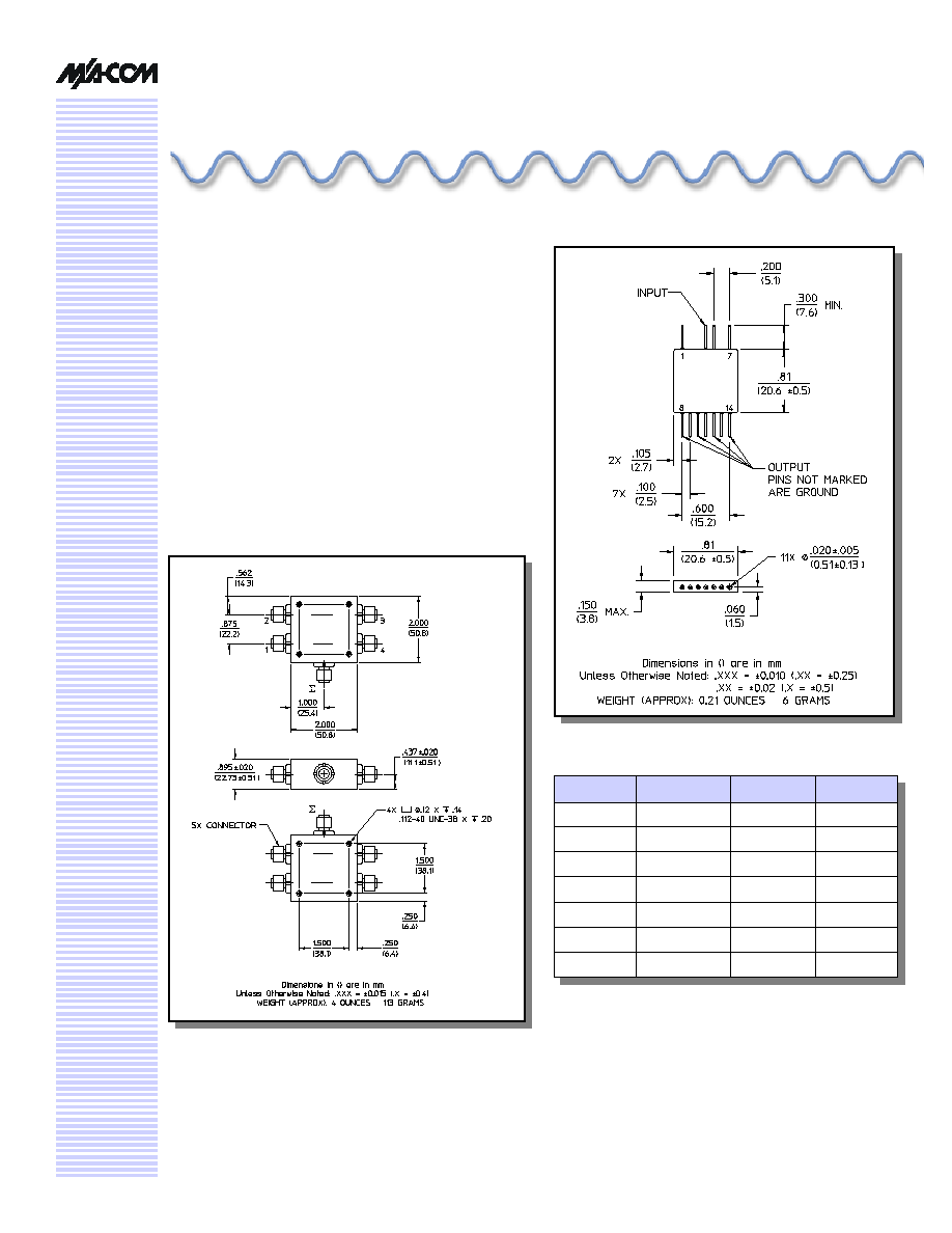
FP-5 (DS-112)
V 3.00
Features
n
Low Loss: 0.6 dB Typical
n
High Isolation: 30 dB Typical
n
Low VSWR: 1.2:1 Typical
n
Impedance: 50 Ohms Nominal
n
Maximum Power Rating or Input Power: 1 Watt Max.
n
Internal Load Dissipation: DS-112 - 0.05 Watts Max.,
DS-312 - 0.25 Watts Max.
n
MIL-STD-202 Screening Available
Description
A Power Divider is ideally a loss less reciprocal device
which can also perform vector summation of two or more
signals and thus is sometimes called a power combiner or
summer.
C-14 (DS-312)
Pin No.
Function
Pin No.
Function
1
GND
8
Output
2
GND
9
GND
3
GND
10
Output
4
Input
11
GND
5
GND
12
Output
6
GND
13
GND
7
GND
14
Output
Pin Configuration (DS-112)

Four-Way Power Divider, 10 - 500 MHz
DS-112/312
V 3.00
M/A-COM Inc. and its affiliates reserve the right to make changes to the product(s)
or information contained herein without notice. M/A-COM makes no warranty,
representation or guarantee regarding the suitability of its products for any
particular purpose, nor does M/A-COM assume any liability whatsoever arising out
of the use or application of any product(s) or information.
Visit www.macom.com for additional data sheets and product information.
n
North America: Tel. (800) 366-2266
n
Asia/Pacific: Tel.+81-44-844-8296, Fax +81-44-844-8298
n
Europe: Tel. +44 (1344) 869 595, Fax+44 (1344) 300 020
2
DS-112 Electrical Specifications
1
: T
A
= -55�C to +85�C
Parameter
Test Conditions
Frequency
Units
Min
Typ
Max
Insertion Loss
(Less Coupling)
10 - 400 MHz
400 - 500 MHz
dB
dB
--
--
--
--
0.75
0.85
Isolation
10 - 500 MHz
dB
25
--
--
Amplitude Balance
10 - 500 MHz
dB
--
--
0.2
Phase Balance
10 - 500 MHz
�
--
--
5
VSWR
All Ports
10 - 25 MHz
25 - 500 MHz
Ratio
Ratio
--
--
--
--
1.5:1
1.35:1
1. All specifications apply with 50 ohm source and load impedance.
DS-312 Electrical Specifications
1
: T
A
= -55�C to +85�C
Parameter
Test Conditions
Frequency
Units
Min
Typ
Max
Insertion Loss
(Less Coupling)
10 - 400 MHz
400 - 500 MHz
dB
dB
--
--
--
--
0.75
0.85
Isolation
10 - 500 MHz
dB
25
--
--
Amplitude Balance
10 - 500 MHz
dB
--
--
0.2
Phase Balance
10 - 500 MHz
�
--
--
2
VSWR
All Ports
10 - 400 MHz
400 - 500 MHz
Ratio
Ratio
--
--
--
--
1.5:1
1.35:1
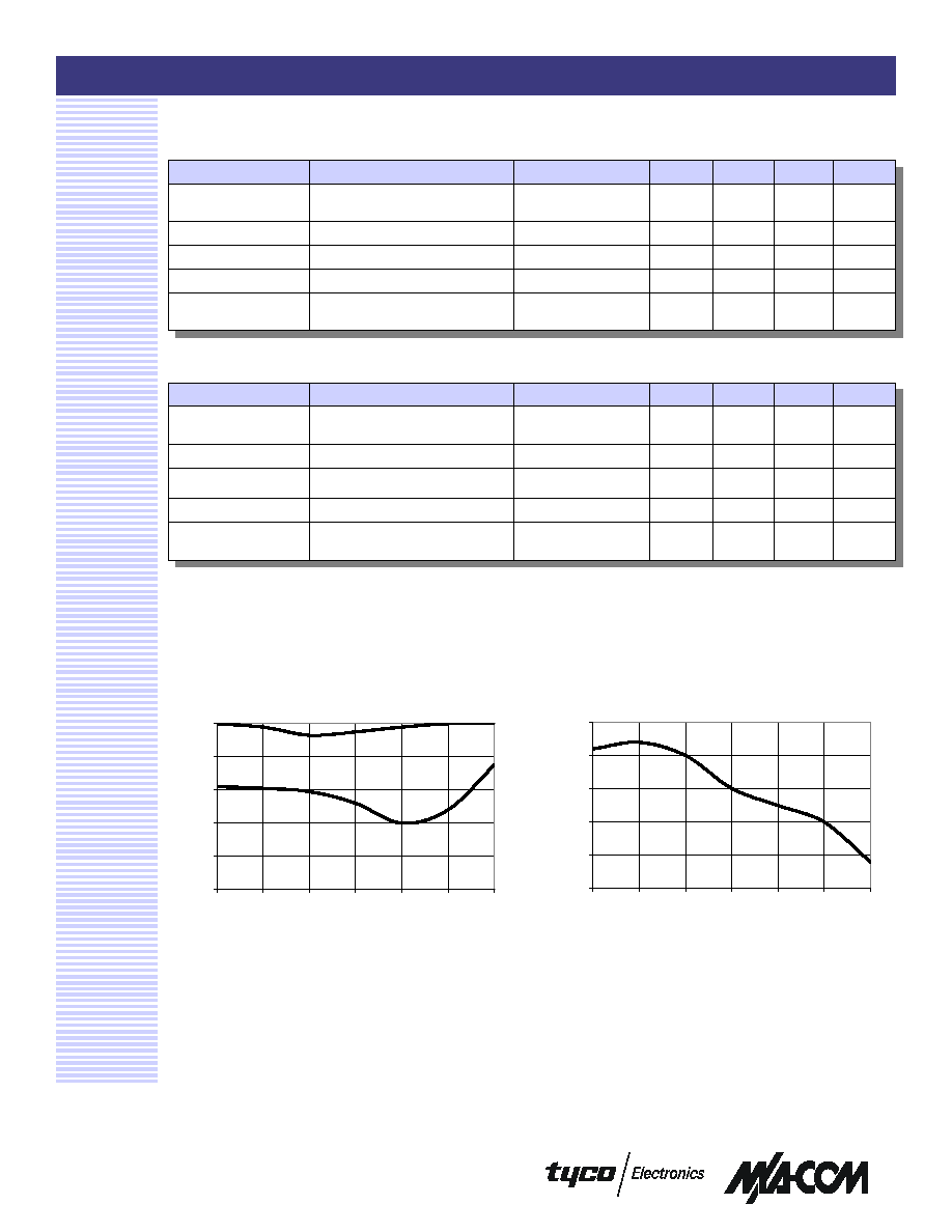
Typical Performance Curves
Isolation
Insertion Loss
0.000
0.200
0.400
0.600
0.800
1.000
5
10
30
100
300
500
700
Frequency (MHz)
Insertion Loss (dB)
20
25
30
35
40
45
5
10
30
100
300
500
700
Frequency (MHz)
Isolation (dB)

Four-Way Power Divider, 10 - 500 MHz
DS-112/312
V 3.00
M/A-COM Inc. and its affiliates reserve the right to make changes to the product(s)
or information contained herein without notice. M/A-COM makes no warranty,
representation or guarantee regarding the suitability of its products for any
particular purpose, nor does M/A-COM assume any liability whatsoever arising out
of the use or application of any product(s) or information.
Visit www.macom.com for additional data sheets and product information.
n
North America: Tel. (800) 366-2266
n
Asia/Pacific: Tel.+81-44-844-8296, Fax +81-44-844-8298
n
Europe: Tel. +44 (1344) 869 595, Fax+44 (1344) 300 020
3
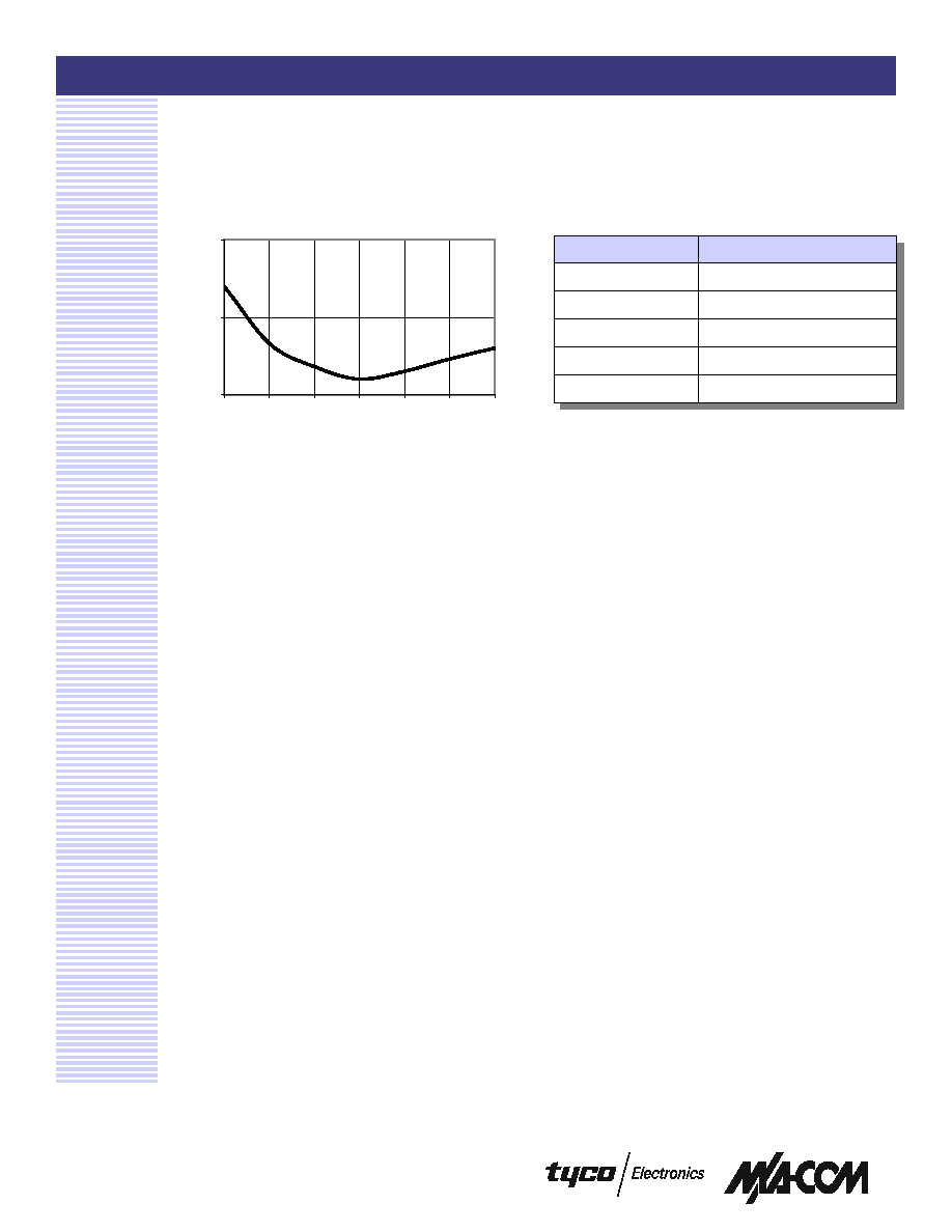
Typical Performance Curves
VSWR
Ordering Information
Part Number
Package
DS-112 PIN
FP-2
DS-312 BNC
C-14
DS-312 TNC
C-14
DS-312 N
C-14
DS-312 SMA
C-14
1
1.5
2
5
10
30
100
300
500
700
Frequency (MHz)
VSWR


