ISO 9001
CERTIFIED
Specifications Subject to Change Without Notice
E-Series HMIC Double Balanced Mixer
1400 - 2000 MHz
EMD40-1800L
Features
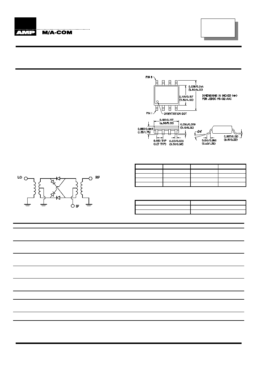
* SOIC-8 package
* IC process
* Low profile
* LO Drive +3dBm to +7dBm
Description
M/A-COM's EMD40-1800L is a passive double
balanced mixer in a low cost, surface mount SOIC-8
package. Fabricated using a mature silicon process
(HMIC), it is ideally suited for high volume cellular and
wireless applications. Typical applications include
frequency up/down conversion, modulation and
demodulation in JDC (1500MHz), DCS (1800MHz)
and PCS (1900MHz).
Schematic
Pin Configuration
Pin Function Pin
Function
1 GND 5 LO
2 IF 6
GND
3 GND 7 GND
4 GND 8 RF
Ordering Information
Part Number
Packaging
EMD40-1800L Tube
EMD40-1800LTR
Tape and Reel
Specifications @ 25
∞C
Frequency Range
1400 - 2000 MHz
Conversion Loss
Maximum
Mean (x)
Sigma (
)
1400 - 1700 MHz
8.0 dB
6.80 dB
0.27
1700 - 2000 MHz
9.5 dB
7.90 dB
0.26
L - R Isolation
Minimum
Typical
1400 - 1700 MHz
28.0 dB
33.5 dB
1700 - 2000 MHz
25.0 dB
28.8 dB
L - I Isolation
Minimum
Typical
1400 - 1700 MHz
23.0 dB
27.2 dB
1700 - 2000 MHz
23.0 dB
27.0 dB
LO VSWR
Maximum
Typical
1400 - 1700 MHz
3.20
2.66
1700 - 2000 MHz
2.90
2.41
RF VSWR
Maximum
Typical
1400 - 1700 MHz
3.00
1.75
1700 - 2000 MHz
2.70
1.71
IF VSWR
Maximum
Typical
DC - 400 MHz
1.80
1.40
Input IP3
Minimum
Typical
1400 - 1700 MHz
8.0 dBm
11.0 dBm
1700 - 2000 MHz
10.0 dBm
14.2 dBm
IF 1.0 dB Bandwidth
DC - 500MHz
Input 1dB Compression
+1.0 dBm
Test conditions: LO drive = +7dBm, IF frequency = 60MHz. Mean and sigma calculated at 1500MHz and 1800MHz. S1229 C
AMP M/A-COM Eurotec * Loughmahon Technology Park * Blackrock * Cork * Ireland * Tel: 353-21-808300 * Fax: 353-21-359935
ISO 9001
CERTIFIED
Specifications Subject to Change Without Notice
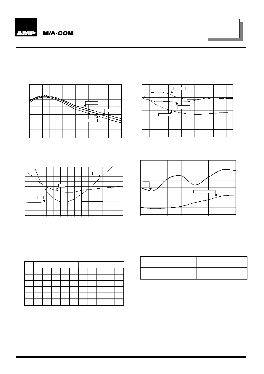
Typical Performance
Over Extended Bandwidth (1100MHz - 2500MHz)
Conversion Loss
Isolation
5.00
6.00
7.00
8.00
9.00
10.00
11.00
12.00
1100
1200
1300
1400
1500
1600
1700
1800
1900
2000
2100
2200
2300
2400
2500
Frequency (MHz)
C
onver
si
on Loss (
d
B)
+7dBm
+5dBm
+3dBm
0.00
5.00
10.00
15.00
20.00
25.00
30.00
35.00
40.00
1100
1200
1300
1400
1500
1600
1700
1800
1900
2000
2100
2200
2300
2400
2500
Frequency (MHz)
Is
olation (dB)
LO to RF
LO to IF
RF to IF
VSWR
IP3 and 1dB Compression
0
0.5
1
1.5
2
2.5
3
3.5
4
4.5
5
1100
1200
1300
1400
1500
1600
1700
1800
1900
2000
2100
2200
2300
2400
2500
RF anf LO Frequency (MHz)
Is
olation (dB)
RF
LO
IF
IF Frequency (MHz)
0.30
43.0
85.0
171
21.
0
64.0
1
06
193
214
235
256
279
300
0.00
2.50
5.00
7.50
10.00
12.50
15.00
17.50
20.00
1200
1400
1600
1800
2000
2200
2400
2500
Frequency (MHz)
Po
w
e
r (d
Bm)
IP3
1 dB Compression
Note: Conversion loss measured with fixed IF frequency of 60MHz. All measurements made with input power of +7dBm.
Spurious Table
(In dBc below IF, assuming down conversion)
nf
LO
+ mf
RF
nf
LO
- mf
RF
0 X 17 16 11 41 X 17 16 11 40
1 12 0 29 36 44 10 0 25 14 32
RF 2 47 39 60 44 43 47 38 53 40 58
(n) 3 54 58 55 45 57 53 51 57 52 49
4 79 66 63 70 72 79 61 62 61 64
0 1 2 3 4 0 1 2 3 4
LO (m)
RF = 1842.5 MHz, -5dBm
LO = 1772.5 MHz, +7dBm
Absolute Maximum Ratings
Parameter Absolute
Maximum
RF Input Power
+17dBm
LO Drive Power
+17dBm
Operating/Storage Temp.
-40
∞C to +85∞C
S 1229 C
AMP M/A-COM Eurotec * Loughmahon Technology Park * Blackrock * Cork * Ireland * Tel: 353-21-808300 * Fax: 353-21-359935