Silicon Double Balanced HMICTM Mixer
MA4EX240L-1225
M/A-COM Division of AMP Incorporated n North America: Tel. (800) 366-2266, Fax (800) 618-8883 n Asia/Pacific: Tel.+85 2 2111 8088, Fax +85 2 2111 8087
n Europe: Tel. +44 (1344) 869 595, Fax+44 (1344) 300 020
www.macom.com
AMP and Connecting at a Higher Level are trademarks.
Specifications subject to change without notice.
V2.00
Features
∑
Low Cost Miniature Plastic Package
∑
Low Conversion Loss:
6.4 dB at 2100 MHz
7.4 dB at 2400 MHz
∑
+3 to +7 dBm LO Drive
∑
HMICTM Process
∑
Silicon Low Barrier Schottky Diodes
∑
DC -400 MHz IF Bandwidth
Description
M/A-COM's MA4EX240L-1225 is a silicon monolithic 1700 -
2500 MHz double balanced mixer in a low cost miniature surface
mount SOT-25 package. The dies uses M/A-COM's unique
HMICTM silicon/glass process to achieve low loss passive ele-
ments while retaining the advantages of low barrier silicon Schot-
tky diodes.
Applications
These mixers are well suited for high volume wireless applications
where small size and repeatability are required. Typical applica-
tions include frequency conversion, modulation, and demodula-
tion for receivers and transmitters in wireless LAN and other data
applications in the 2.4 GHz 15M band.
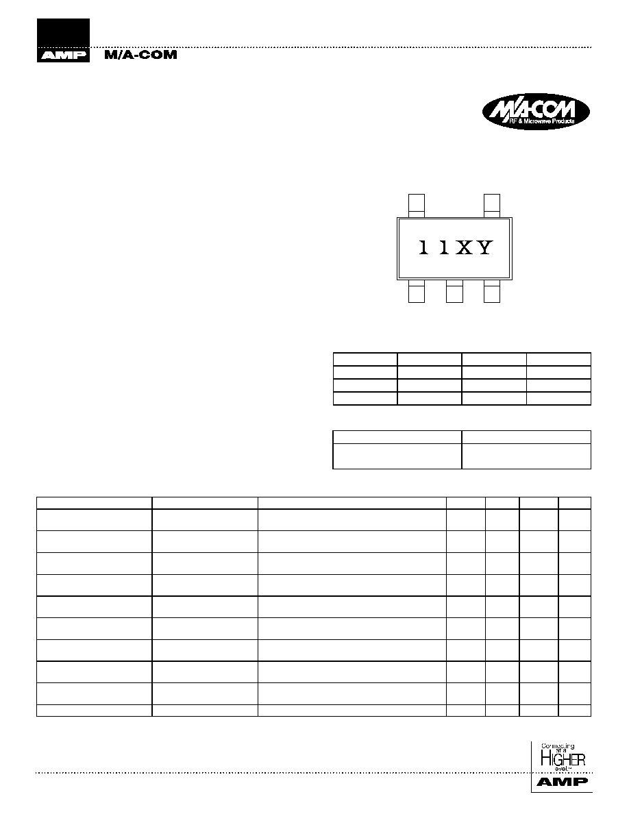
SOT-25 Outline
Pin Configuration
Electrical Specifications @ +25∞C
Silicon Double Balanced HMICTM
Mixer 1700 - 2500 MHz
MA4EX240L-1225
PIN
Function
PIN
Function
1
Gnd
4
RF
2
Gnd
5
LO
3
IF
--
--
Ordering Information
Model No.
Package
MA4EX240L-1225
Bulk
MA4EX240L-1225T
Tape and Reel
1
2
3
5
4
Parameter
Frequency Range
Test Conditions
Units
Min.
Typ.
Max.
Conversion Loss
2100 MHz
1700-2500 MHz
LO Drive = +5 dBm, f
LO
= f
RF
+ f
IF
RF = -10 dBm, IF = 60 MHz
dB
dB
--
--
6.4
7.0
8.2
9.5
L - R Isolation
2100 MHz
1700-2500 MHz
LO Drive = +5 dBm
RF Level = -10 dBm
dB
dB
14
--
17.5
14
--
--
L - I Isolation
2100 MHz
1700-2500 MHz
LO Drive = +5 dBm
RF Level = -10 dBm
dB
dB
--
--
23
23
--
--
R - I Isolation
2100 MHz
1700-2500 MHz
LO Drive = +5 dBm
RF Level = -10 dBm
dB
dB
--
--
13.5
13
--
--
LO VSWR
2100 MHz
1700-2500 MHz
LO Drive = +5 dBm
RF Level = -10 dBm
--
--
--
--
2.1
2.1
--
--
RF VSWR
2100 MHz
1700-2500 MHz
LO Drive = +5 dBm
RF Level = -10 dBm
--
--
--
--
1.3
2.0
--
--
IF VSWR
DC - 500 MHz
LO Drive = +5 dBm
IF Level = -10 dBm
--
--
--
--
1.3
--
--
--
Input IP3
2100 MHz
1700-2500 MHz
LO Drive = +5 dBm, f
RL
= f
LO
-F
IF
IF = 60 MHz
dBm
dBm
+10
+8
+13.0
+12.0
--
--
Input 1 dB Compression
2100 MHz
1700-2500 MHz
LO Drive = +5 dBm
IF = 60 MHz
dBm
dBm
--
--
+1.0
+1.0
--
--
IF 1 dB Bandwidth
0-400 MHz
LO = 2050 MHz @ +5 dBm
MHz
--
400
--
Silicon Double Balanced HMICTM Mixer
MA4EX240L-1225
M/A-COM Division of AMP Incorporated n North America: Tel. (800) 366-2266, Fax (800) 618-8883 n Asia/Pacific: Tel.+85 2 2111 8088, Fax +85 2 2111 8087
n Europe: Tel. +44 (1344) 869 595, Fax+44 (1344) 300 020
www.macom.com
AMP and Connecting at a Higher Level are trademarks.
Specifications subject to change without notice.
V2.00
Case Style
5
1 0
1 5
2 0
2 5
3 0
1 7 0 0
1 9 0 0
2 1 0 0
2 3 0 0
2 5 0 0
F R E Q U E N C Y ( M H z )
I
S
O
L
AT
I
O
N (
d
B)
0
2
4
6
8
1 0
1 2
1 4
1 6
1 8
2 0
1 7 0 0
1 9 0 0
2 1 0 0
2 3 0 0
2 5 0 0
F R E Q U E N C Y ( M H z )
ABS
O
L
UT
E
P
O
W
E
R (
d
Bm
)
1 . 0
1 . 5
2 . 0
2 . 5
3 . 0
3 . 5
4 . 0
1 7 0 0
1 9 0 0
2 1 0 0
2 3 0 0
2 5 0 0
F R E Q U E N C Y ( M H z )
VSWR
5 . 0
5 . 5
6 . 0
6 . 5
7 . 0
7 . 5
8 . 0
8 . 5
9 . 0
1 7 0 0
1 9 0 0
2 1 0 0
2 3 0 0
2 5 0 0
F R E Q U E N C Y ( M H z )
L
O
SS (
d
B
)
Absolute Maximum Rating
1
Parameter
Maximum Ratings
Operating Temperature
-40∞C to +85∞C
Storage Temperature
-65∞C to +150∞C
Incident LO Power
+20 dBm
Incident RF Power
+20 dBm
1. Exceeding these limits may cause permanent damage.
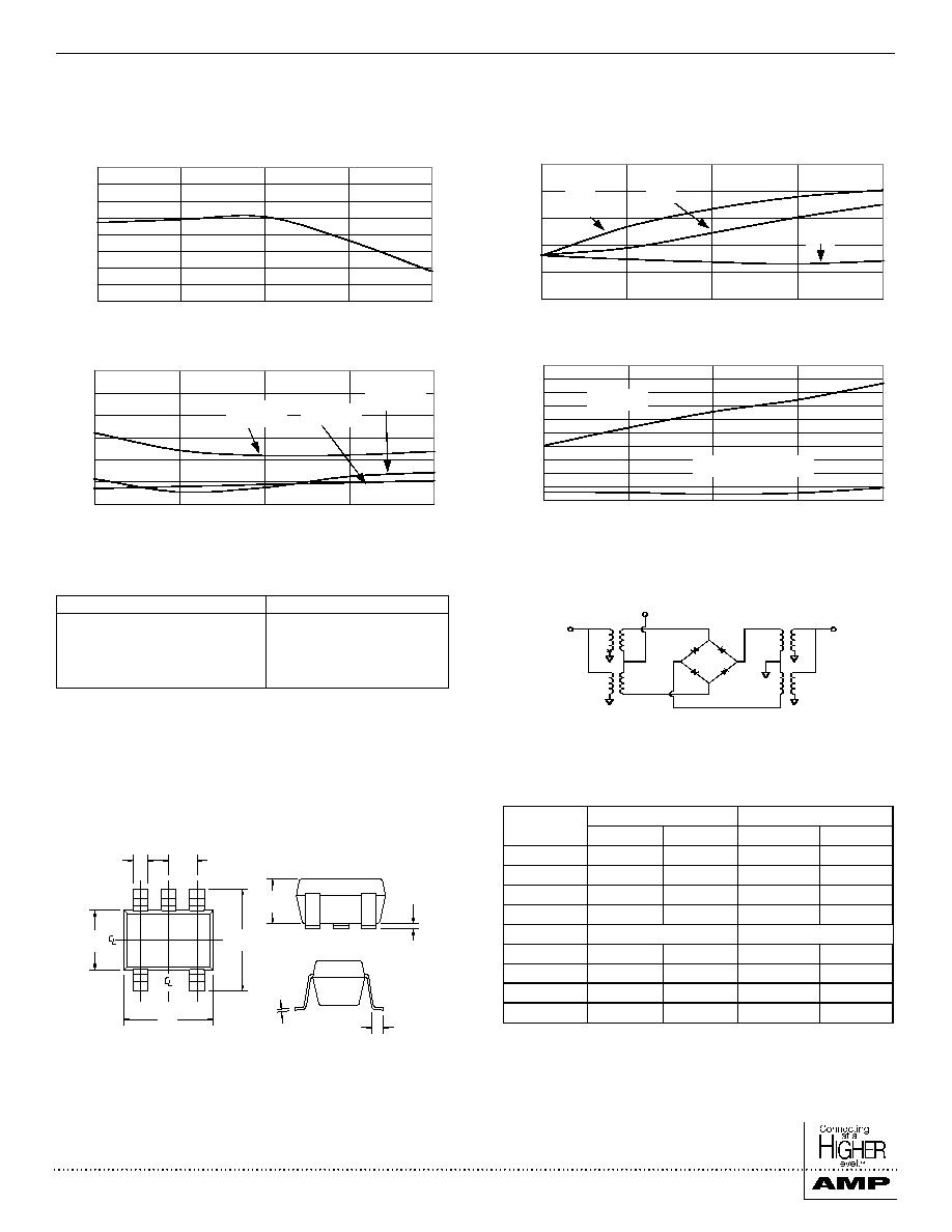
Typical Performance Curves
Conversion Loss
Isolation
Typical VSWR
IP3 & 1dB Compression Point
(LO Drive = +5 dBm, RF = -10 dBm, IF = 60 MHz)
R-I
L-R
L-I
RF VSWR
LO VSWR
IF VSWR
Schematic
RF
IF
LO
SOT-25
SOT-25
1,2
H
C
E
TYP.
5X
F
B
D
G
J
A
INCHES
MILLIMETERS
DIM
MIN
MAX
MIN
MAX
A
0.1103
0.1181
2.8
3.10
B
0.1023
0.1181
2.6
3.00
C
0.0355
0.0512
0.9
1.30
D
0.0591
0.0669
1.5
1.7
E
0.0374 Typ.
0.95 Typ.
F
0.0138
0.0197
0.35
0.5
G
0.0031
0.0079
0.08
0.20
H
0.0020
0.0059
0.05
0.15
J
0.0138
0.0216
0.35
0.55
1. Dimensions do not include mold flash, protrusion or gate burrs
which shall not exceed 0.0098 in (.25mm) per side.
2. Lead Coplanarity is 0.003 (0.08) max.
IP3
1 dB Comp.