E-Series RF 1:1 Transformer
760 - 960 MHz
ETC1-1-6
M/A-COM, Inc.
North America:
Tel. (800) 366-2266
s
Asia/Pacific: Tel. +81 (03) 3226-1671
s
Europe: Tel. +44 (1344) 869 595
Fax (800) 618-8883
Fax +81 (03) 3226-1451
Fax +44 (1344) 300 020
1
Specifications Subject to Change Without Notice.
V3.00
Features
Surface Mount
1:1 Impedance Ratio
Description
M/A-COM's ETC1-1-6 is a 1:1 RF transformer in a
low-cost, surface mount package. Ideally suited for high
volume cellular and wireless applications.
Schematic
Specifications
@ 25∞C
Frequency Range: 760 - 960 MHz
Ordering Information
Part No.
Packaging
ETC1-1-6
Tubes
ETC1-1-6TR
Tape & Reel
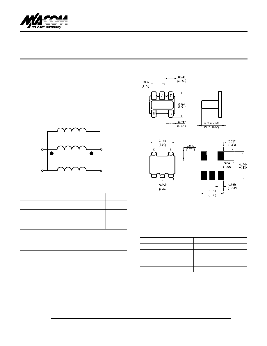
SM-22
Pin Configuration
Pin No.
Function
1
Secondary dot
2
Not connected
3
Secondary
4
Primary
5
Primary dot
q
q
S 0758 E
Dimensions in ( ) are in mm.
Unless Otherwise Noted: .x = ±0.04 (1.00)
.xx = ±0.02 (0.50)
.xxx = ±0.010 (0.250)
PRI
SEC
Parameter
Maximum
Mean (x) Sigma (
)
Insertion Loss (f
L
- f
U
)
760 - 960 MHz
2.0 dB
0.22
0.096
Amplitude Unbalance
760 - 960 MHz
1.2 dB
≠
≠
Phase Unbalance
760 - 960 MHz
5∞
≠
≠
Note: Mean and sigma calculated from average loss at @ (f
U
- f
L
)/2 + f
L
.

E-Series RF 1:1 Transformer
ETC1-1-6
V3.00
M/A-COM, Inc.
North America:
Tel. (800) 366-2266
s
Asia/Pacific: Tel. +81 (03) 3226-1671
s
Europe: Tel. +44 (1344) 869 595
Fax (800) 618-8883
Fax +81 (03) 3226-1451
Fax +44 (1344) 300 020
2
Specifications Subject to Change Without Notice.
Absolute Maximum Ratings
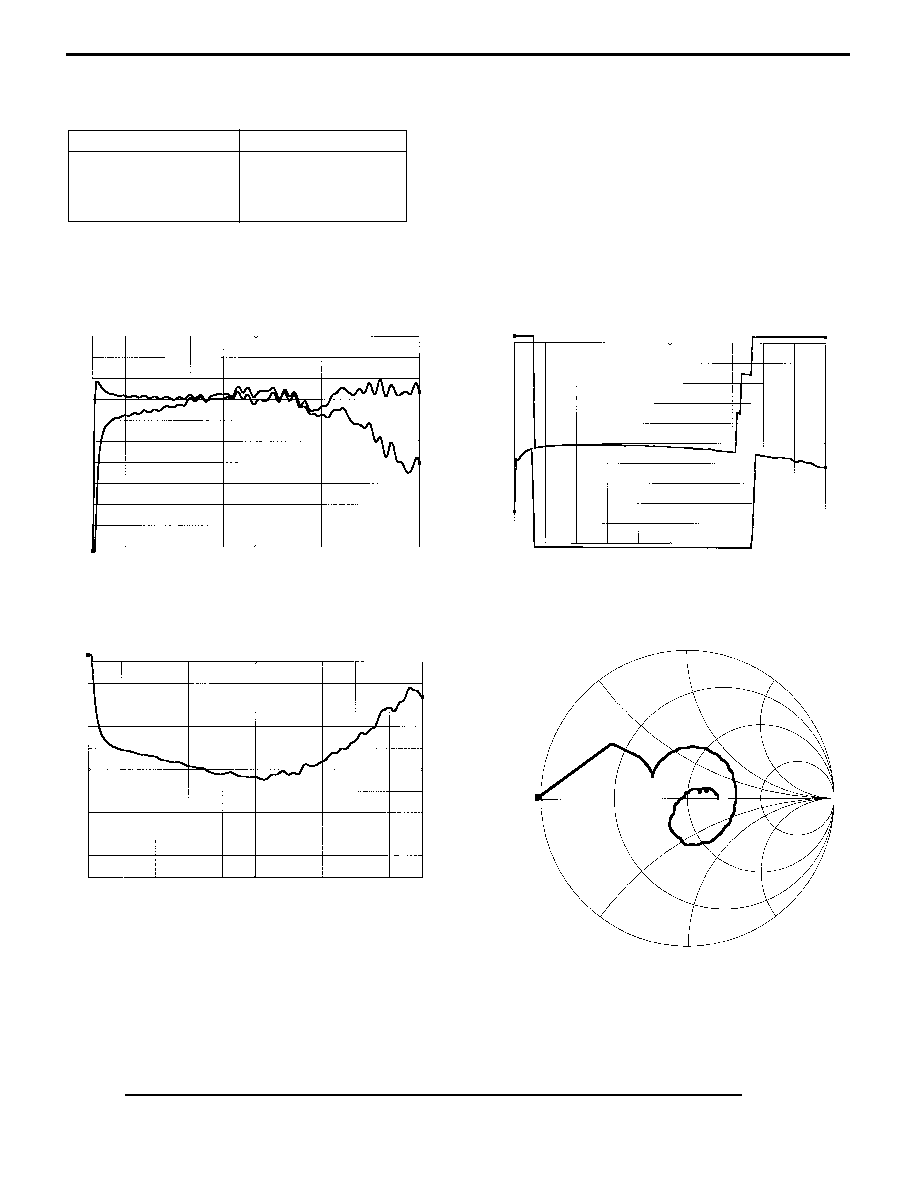
INSERTION LOSS vs FREQUENCY
PHASE UNBALANCE vs FREQUENCY
Parameter
Absolute Maximum
Parameter
Absolute Maximum
RF Power
250 mW
DC Current
30 mA
Operating/Storage Temp.
-20∞C to +85∞C
Typical Performance
Over Extended Bandwidth (30 kHz - 3 GHz)
AMPLITUDE UNBALANCE vs FREQUENCY
INPUT IMPEDANCE vs FREQUENCY
Note: All measurements performed on Hewlett Packard 8753D Network Analyzer (201 sample points, linear scale) in a 50 ohm coplanar waveguide
environment. Tables created using MDS software.
S-Parameter data available by E-Mail. Send your request to: eurotec@corp.macom.com.
B1
A1
≠10.0
unit4s21
0.0B
≠10.0
unit4s31
0.0A
A1
B1
0.0
avgpb2
360.0B
0.0
avgpb1
360.0A
30.0 kHz
freq
3.0 GHz A
A1
≠5.0
unit4s21≠unit4s31
5.0A
30.0 kHz
freq
3.0 GHz B
Y≠FS= 1.0
avgiprl
B
30.0 kHz
freq
3.0 GHz A
30.0 kHz
freq
3.0 GHz B
30.0 kHz
freq
3.0 GHz A
30.0 kHz
freq
3.0 GHz B
INSERTION LOSS (0 to -10 dB) vs FREQ (30 kHz TO 3 GHz)
PHASE UNBALANCE (0 to 369 deg) vs FREQ (30 kHz to 3 GHz)
AMP UNBALANCE (5 to -5 dB) vs FREQ (30 kHz to 3 GHz)
INPUT IMPEDANCE on SMITH CHART; FREQ (30 kHz to 3 GHz)
B1

