Low Cost SMT Low Pass Filter DC-1000 MHz FL07-0001-G
M/A-COM Division of AMP Incorporated
s
North America: Tel. (800) 366-2266, Fax (800) 618-8883
s
Asia/Pacific: Tel.+85 2 2111 8088,
Fax +85 2 2111 8087
s
Europe: Tel. +44 (1344) 869 595, Fax+44 (1344) 300 020
www.macom.com
AMP and Connecting at a Higher Level are trademarks.
Specifications subject to change without notice.
S1514A V1.00
Features
∑
Small Size and Low Profile
∑
Industry Standard SOIC-8 SMT Plastic Package
∑
Superior Repeatability
∑
Typical Insertion Loss 0.5 dB
∑
Typical Rejection 20dB
∑
2 Watt Power Handling
Description
M/A-COM's FL07-0001-G is an IC-based monolithic low pass
filter in a low cost SOIC-8 plastic package. This filter is ideally
suited for applications where small size, low cost and low loss are
required.
Typical applications include base station switching networks and
portable phones where size and PCB real estate are at a premium.
Available in tape and reel.
The FL07-0001-G is fabricated using a passive-integrated circuit
process. The process features full-chip passivation for increased
performance and reliability.
Low Cost SMT Low Pass Filter
DC - 1000 MHz
FL07-0001-G
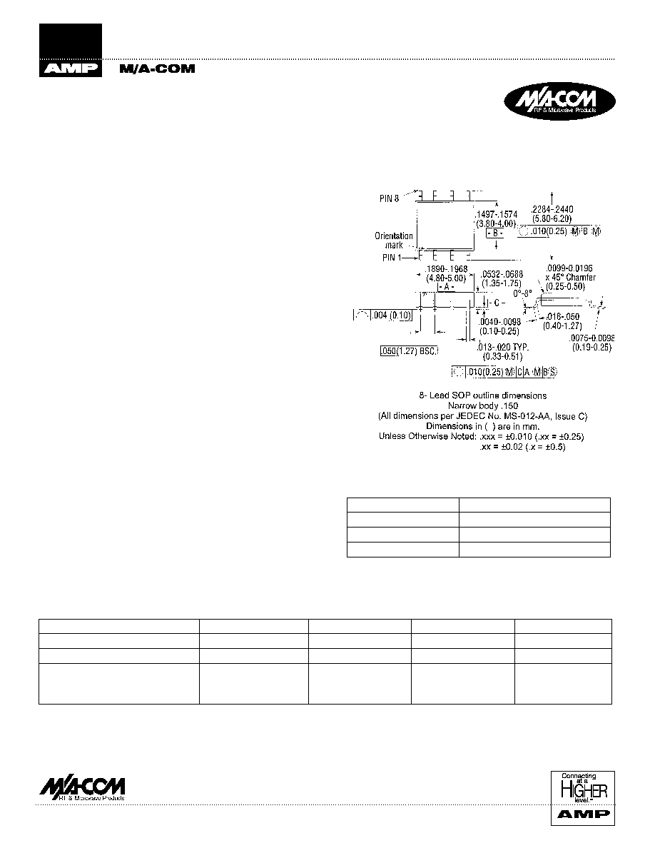
SO-8
Typical Electrical Specifications
1
, T
A
= +25∞C
Parameter
Units
Min
Typ
Max
Insertion Loss: DC-1000MHz
dB
--
0.5
1.0
VSWR: DC-1000 MHz
1.3:1
1.6:1
Rejection: 1800-3500 MHz
2000-3000 MHz
dB
dB
15
20
20
27
1. All specifications apply with a 50-Ohm source and load impedance.
* If specific reel size is required, consult factory for part number
assignment.
Ordering Information
Part Number
Package
FL07-0001-G
SOIC 8-Lead Plastic Package
FL07-0001-G-TR
Forward Tape and Reel*
FL07-0001-G-RTR
Reverse Tape and Reel*
Low Cost SMT Low Pass Filter DC-1000 MHz FL07-0001-G
M/A-COM Division of AMP Incorporated
s
North America: Tel. (800) 366-2266, Fax (800) 618-8883
s
Asia/Pacific: Tel.+85 2 2111 8088,
Fax +85 2 2111 8087
s
Europe: Tel. +44 (1344) 869 595, Fax+44 (1344) 300 020
www.macom.com
AMP and Connecting at a Higher Level are trademarks.
Specifications subject to change without notice.
S1514A V1.00
1. Exceeding these limits may cause permanent damage.
Absolute Maximum Ratings
1
Parameter
Absolute Maximum
Input Power
2 W CW
Operating Temperature
-40∞C to +85∞C
Storage Temperature
-65∞C to +150∞C
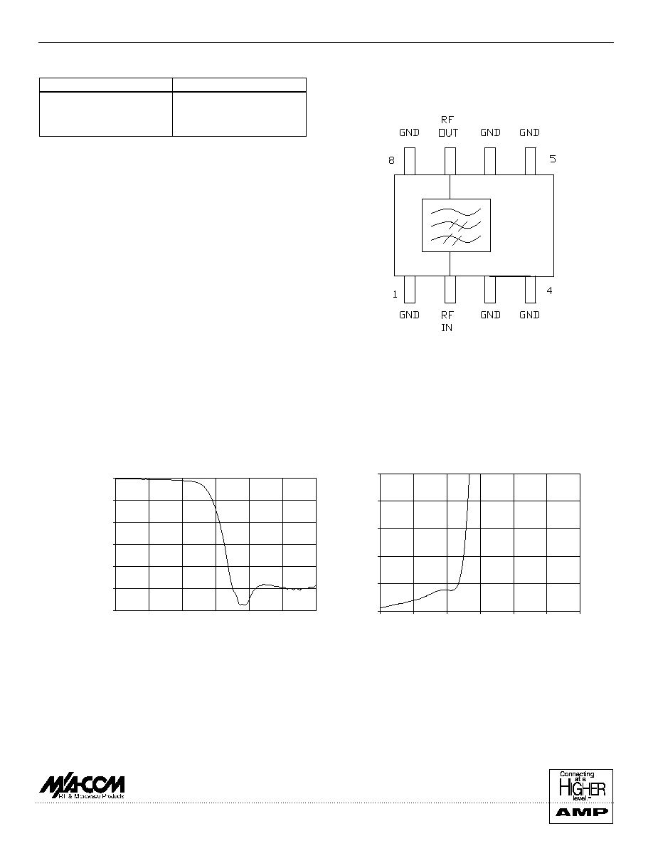
Functional Diagram
Insertion Loss vs Frequency
-30.0
-25.0
-20.0
-15.0
-10.0
-5.0
0.0
0.0
500.0
1000.0
1500.0
2000.0
2500.0
3000.0
Frequency (MHz)
dB
Typical Performance
@ +25∞C
VSWR vs Frequency
1.0
1.2
1.4
1.6
1.8
2.0
0.0
500.0
1000.0
1500.0
2000.0
2500.0
3000.0
Frequency (M H z)
All unused pins must be RF and DC grounded.
Pins 1 and 4 are thermal ground contacts.