 | –≠–ª–µ–∫—Ç—Ä–æ–Ω–Ω—ã–π –∫–æ–º–ø–æ–Ω–µ–Ω—Ç: IM02TS | –°–∫–∞—á–∞—Ç—å:  PDF PDF  ZIP ZIP |
IM Relay
The Best Rela
y
tion
Slim line AND low profile
2 pole telecom/signal relay, polarized
Through Hole Types (THT), standard version
with 5.08 mm, narrow version with 3.2 mm between
the terminal rows
or
Surface Mount Type (SMT)
Relay types:
non-latching with 1 coil
latching with 1 coil
Features
- Telecom/signal relay (dry circuit, test access, ringing)
- Slim line10 x 6 mm, 0.39 x 0.24 inch
- Low profile 5.65 mm, 0.222 inch
- Minimum board-space 60 mm
2
- Switching current 2 A
- 2 changeover contacts (2 form C / DPDT)
- Bifurcated contacts, gold plated
- High sensitivity results in low nominal power consumption
140 mW for non latching
100 mW for latching version
- High surge capability (1.2/50 µs and 10/700 µs) meets
Bellcore GR 1089, FCC Part 68 and ITU-T K20
≥1500 V between open contacts
≥ 2500 V between coil and contacts
- High mechanical shock resistance
up to 300 G functional
up to 500 G survival
Typical applications:
- Communications equipment
Linecard application ≠ analog, ISDN, xDSL,
PABX
Voice over IP
- Office and business equipment
- Measurement and control equipment
- Consumer electronics
Set top boxes, HiFi
- Medical equipment
Options:
Surge capability ≥ 2500 V between open contacts
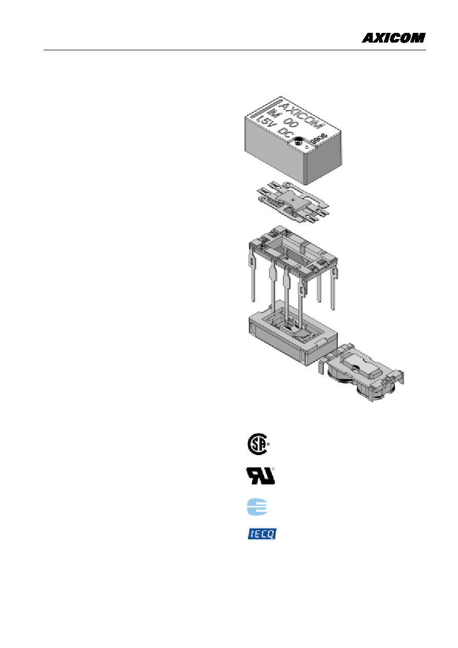
IM Relay
2
Insulation category:
Supplementary insulation according IEC/EN 60950 and UL 1950
Working voltage
£ 300 Vrms
Mains supply voltage
SMT: 250 Vrms
THT: 200 Vrms
Repetitive peak voltage
2500 V
Pollution degree:
External: 2
Internal:
1
Flammability classification:
V-0
Maximum operating temperature: 85∞C
CSA-C22.2 No. 14-95 File No. 169679-1079886
CSA-C22.2 No. 950-95
UL 508 File No. E111441
UL 1950 3rd ed.
QC 160501-CH0001
IEC/EN60950 IEC Ref. Cert. No. 1176
CECC 16501-003
3
IM Relay
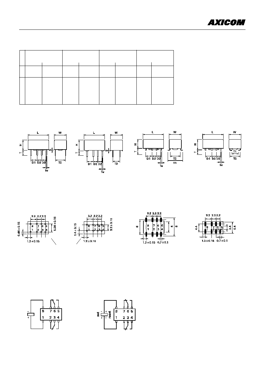
THT Version
Mounting hole layout
View onto the component side of the PCB
(top view)
Terminal assignment
Relay - top view
Non-latching type,
not energized condition
Dimensions
IM THT
IM THT
IM SMT
IM SMT
Standard
Narrow
Gull Wings
J-Legs
mm
inch
mm
inch
mm
inch
L
10
±
0.08 0.393
±
0.003 10
±
0.08 0.393
±
0.003 10
±
0.08 0.393
±
0.003 10
±
0.08 0.393
±
0.003
W 6
±
0.08
0.236
±
0.003 5.7
±
0.3
0.224
±
0.012 6
±
0.08
0.236
±
0.003 6
±
0.08 0.236
±
0.003
H 5.65 -0.2 0.222 -0.008 5.85 -0.15 0.230 -0.006 5.65 -0.2
0.222 -0.008 5.65 -0.2 0.222 -0.008
T 3.2
0.125
3.2
0.125
N/A
N/A
N/A
N/A
T1 N/A
N/A
N/A
N/A
7.5
±
0.3
0.295
±
0.011 2.8
±
0.2 0.110
±
0.007
T2 5.08
±
0.1 0.200
±
0.004 3.2
±
0.1
0.126
±
0.006 5.08
±
0.1 0.200
±
0.004 5.08
±
0.1 0.200
±
0.004
D1 3.2
±
0.15 0.126
±
0.006 3.2
±
0.15 0.126
±
0.006 3.2
±
0.15 0.126
±
0.006 3.2
±
0.15 0.126
±
0.006
D2 2.2
±
0.15 0.087
±
0.006 2.2
±
0.15 0.087
±
0.006 2.2
±
0.15 0.087
±
0.006 2.2
±
0.15 0.087
±
0.006
Tw 0.4
0.015
0.4
0.015
0.4
0.015
0.4
0.015
S 0.3
±
0.05 0.011
±
0.002 0.3
±
0.05 0.011
±
0.002 N/A
N/A
N/A
N/A
SMT Version
Gull Wings
J Legs
Solder pad layout
View onto the component side of the PCB
(top view)
Gull Wings
J Legs
ÿ min. 0.75
Latching type, 1 coil
reset condition
Standard version
Narrow version
Standard version
Narrow version
1.5
1.13
3.4
0.15
140
16
IM00
3
2.1
6.8
0.30
140
64
IM01
4.5
3.15
10.3
0.45
140
145
IM02
5
3.5
11.4
0.50
140
178
IM03
6
4.2
13.7
0.60
140
257
IM04
9
6.3
20.4
0.90
140
574
IM05
12
8.4
27.3
1.20
140
1028
IM06
24
16.8
45.6
2.40
200
2880
IM07
Coil Data (values at 23∞C)
Nominal
Operate/set voltage range
Release/
Nominal power
Resistance
Relay code
voltage
reset voltage
consumption
Unom
Minimum
Maximum
Minimum
voltage U
I
voltage U
II
Vdc
Vdc
Vdc
Vdc
mW
W / ± 10 %
non-latching
1 coil
latching
1 coil
1.5
1.13
4.1
- 1.13
100
23
IM40
3
2.25
8.1
- 2.25
100
90
IM41
4.5
3.38
12.1
- 3.38
100
203
IM42
5
3.75
13.5
- 3.75
100
250
IM43
6
4.5
16.2
- 4.50
100
360
IM44
9
6.75
24.2
- 6.75
100
810
IM45
12
9.00
32.3
- 9.00
100
1440
IM46
24
18.00
41.9
- 18.00
200
2880
IM47
Further coil versions are available on request.
IM Relay
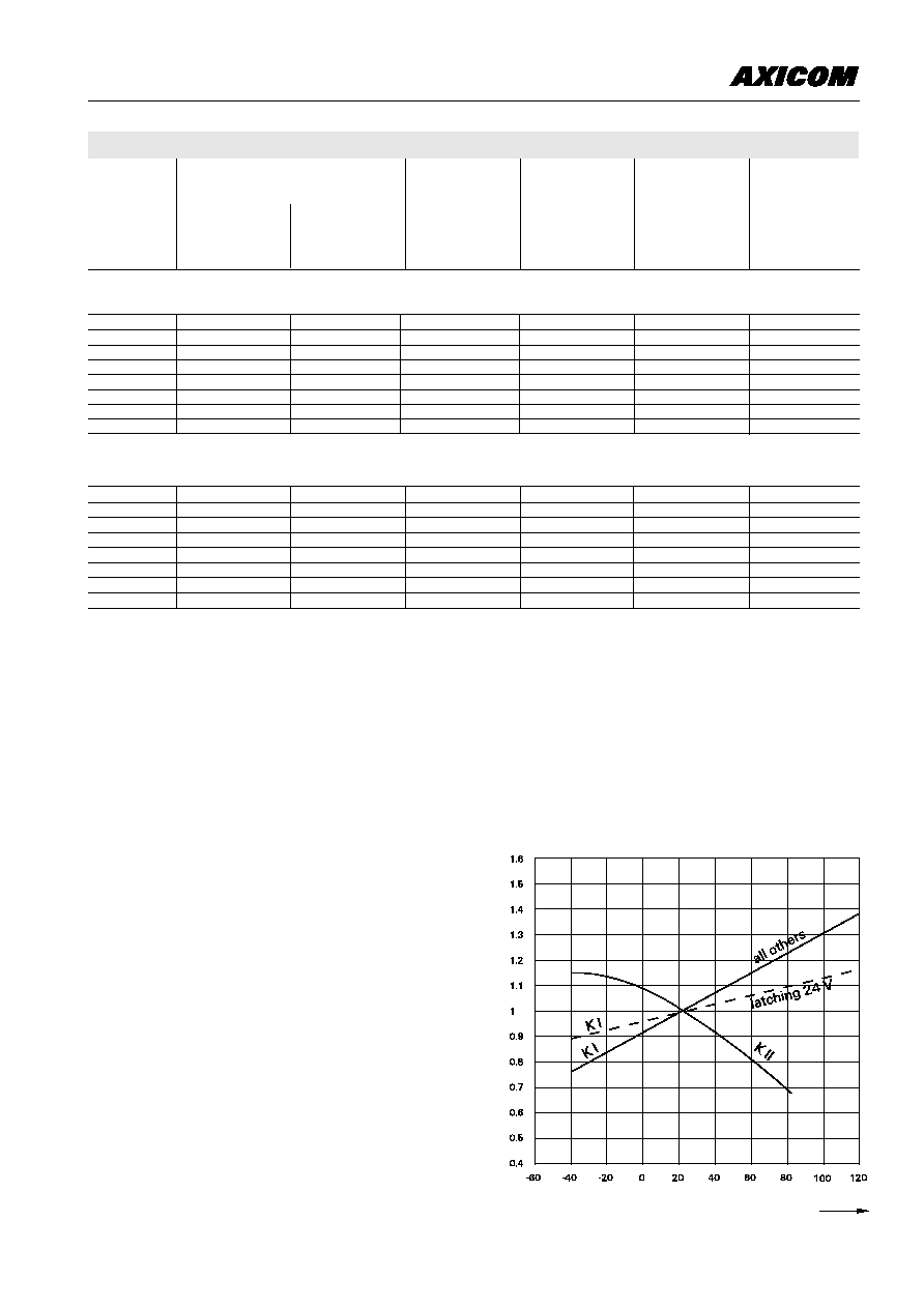
Ambient temperature t
amb
[∞C]
4
U
I
=
Minimum voltage at 23∞ C after pre-energizing
with nominal voltage without contact current
U
II
=
Maximum continous voltage at 23∞
The operating voltage limits U
I
and U
II
depend on
the temperature according to the formula:
U
I tamb
=
K
I
∑ U
I 23∞ C
and
U
II tamb
=
K
Il
∑ U
Il 23∞ C
t
amb
= Ambient temperature
U
I tamb
= Minimum voltage at ambient temperature, t
amb
U
II tamb
= Maximum voltage at ambient temperature, t
amb
k
I
,
k
II
= Factors (dependent on temperature), see diagram
IM Relay
Contact Data
Number of contacts and type
Contact assembly
Contact material
Limiting continuous current at max. ambient temperature
Maximum switching current
Maximum swichting voltage
Maximum switching capacity
Thermoelectric potential
Initial contact resistance / measuring condition: 10 mA / 20 mV
Electrical endurance at contact application 0
(£ 30 mV / £ 10 mA)
cable load open end
Resistive load
at 125Vdc / 0.24 A - 30 W
at 220 Vdc / 0.27 A - 60 W
at 250 Vac / 0.25 A - 62.5 VA
at 30 Vdc / 1 A - 30 W
at 30 Vdc / 2 A - 60 W
Mechanical endurance
UL/CSA ratings
2 changeover contacts
Bifurcated contacts
Palladium-ruthenium, gold-covered
2 A
2 A
220 Vdc
250 Vac
60 W, 62.5 VA
< 10 mV
< 50 mW
min. 2.5 x 10
6
operations
min. 2.0 x 10
6
operations
min. 5 x 10
5
operations
min. 1 x 10
5
operations
min. 1 x 10
5
operations
min. 5 x 10
5
operations
min. 1 x 10
5
operations
typ. 10
8
operations
30 Vdc / 2 A
220 Vdc / 0.27 A
120 Vdc / 0.5 A
250 Vac / 0.25 A
5
Capacitance
between coil and contacts
between adjacent contact sets
between open contacts
RF Characteristics
Isolation at 100 / 900 MHz
Insertion loss at 100 / 900 MHz
V.S.W.R. at 100 / 900 MHz
max. 2 pF
max. 2 pF
max. 1 pF
- 37.0 dB / - 18.8 dB
- 0.03 dB / - 0.33 dB
1.06 / 1.49
High Frequency Data
* High Dielectric Version ,,C"
Insulation
Insulation resistance at 500 VDC
Dielectric test voltage (1 min)
between coil and contacts
between adjacent contact sets
between open contacts
Surge voltage resistance
according to Bellcore TR-NWT-001089 (2 / 10 ms)
between coil and contacts
between adjacent contact sets
between open contacts
according to FCC 68 (10 / 160 ms)
between coil and contacts
between adjacent contact sets
between open contacts
> 10
9
W
> 10
9
W
1800 Vrms
1800 Vrms
1000 Vrms
1800 Vrms
1000 Vrms
1500 Vrms
2500 V
2500 V
1500 V
2500 V
1500 V
2500 V
2500 V
2500 V
1500 V
2500 V
1500 V
2500 V
Standard Version
High Dielectric Version