 | –≠–ª–µ–∫—Ç—Ä–æ–Ω–Ω—ã–π –∫–æ–º–ø–æ–Ω–µ–Ω—Ç: MA46584 | –°–∫–∞—á–∞—Ç—å:  PDF PDF  ZIP ZIP |

M/A-COM Division of AMP Incorporated
s
North America: Tel. (800) 366-2266, Fax (800) 618-8883
s
Asia/Pacific: Tel.+85 2 2111 8088,
Fax +85 2 2111 8087
s
Europe: Tel. +44 (1344) 869 595, Fax+44 (1344) 300 020
www.macom.com
AMP and Connecting at a Higher Level are trademarks.
The Preliminary Specification Data Sheet contains typical electrical specifications which may change prior to final introduction.
V1.00
Beam Lead Gallium Arsenide Tuning Varactor Diode
ML46580S-992
Features
∑
Constant Gamma of 1.25
∑
Strong Beam Construction
∑
Low Parasitic Capacitance
∑
High Q
∑
Close Capacitance Tracking
Description
The ML46580S-992 is a Gallium Arsenide Beam Lead Tuning
Varactor having a Hyperabrupt junction with a resultant constant
gamma characteristic. The constant gamma, high Q values and the
elimination of package parasitics are extremely beneficial for the
linear tuning of voltage controlled oscillators at frequencies above
20 GHz.
This device has been tested previously for space application in
accordance with the requirements of ESA Generic Specifications
PSS-01-608 and ESA/SCC 5010.
High Reliability Beam Lead diodes can be supplied using the
same procedures established for chip diodes. These procedures
detailed in M/A-COM control document MP3021-001 incorpo-
rate the essential elements of ESA/SCC 5010.
M/A-COM can also provide Gallium Arsenide Beam Lead Tun-
ing Varactor diodes with a constant gamma of 1.0 and also with
capacitance up to 2pF.
The Semiconductor Master Catalogue, available on request, con-
tains detailed information of the following additional Tuning
Varactor types many of which are suitable for space application.
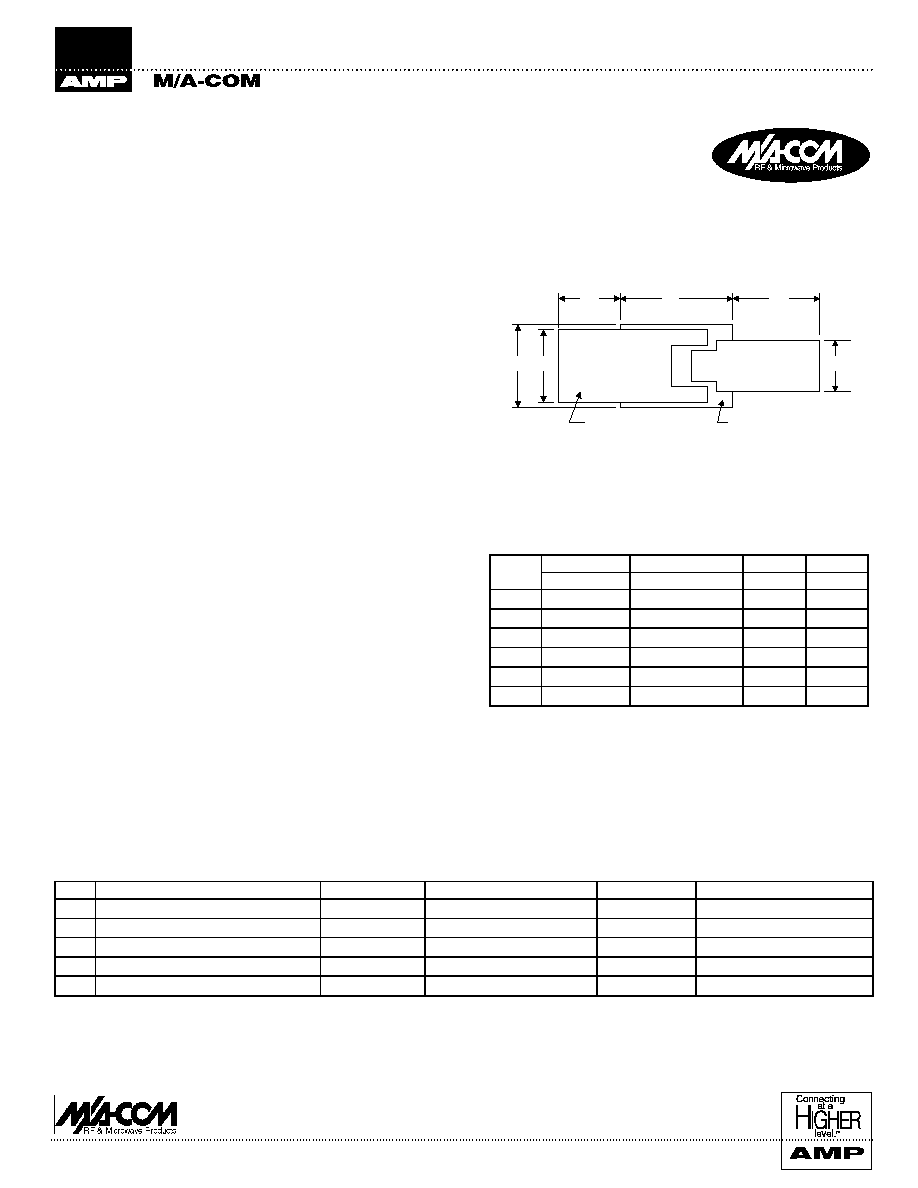
Package Outline
High Reliability Semiconductor ≠ Beam Lead
Gallium Arsenide Tuning Varactor Diode
ML46580S-992
Maximum Ratings (Tamb = +25∞C)
C
E
B
A
B
D
F
C A T H O D E B E A M
D I E T H I C K N E S S
INCHES
MILLIMETERS
DIM
Min.
Max.
Min.
Max.
A
0.012
0.014
0.305
0.356
B
0.010
--
0.254
--
C
0.006
0.008
0.152
0.203
D
0.004
0.006
0.102
0.152
E
0.007
0.009
0.178
0.229
F
--
0.004
0.305
0.1026
∑
Surface Mount (SOT-23) Tuning Varactors
∑
Axial Lead Tuning Varactors
∑
Silicon Abrupt and Hyperabrupt Junction Tuning Varactors
∑
GaAs Abrupt Junction Tuning Varactors
∑
GaAs Hyperabrupt Junction Tuning Varactors with Constant
Gamma 0.75, 1.25, 1.5
No.
Characteristics
Symbol
Maximum Ratings
Units
Remarks
1
Power Dissipation
P
O
25.0
mW
See Note 1
2
Reverse Voltage
V
R
18
V
3
Forward Current
I
F
50
mA
See Note 2
4
Operating Temperature
T
OP
-65 to +150
∞C
5
Storage Temperature
T
STO
-65 to +150
∞C
Notes:
1. Derate linearly to 0 mW from 25∞C to 150∞C
2. Derate linearly to 0 mA from 25∞C to 150∞C
Preliminary Specifications

M/A-COM Division of AMP Incorporated
s
North America: Tel. (800) 366-2266, Fax (800) 618-8883
s
Asia/Pacific: Tel.+85 2 2111 8088,
Fax +85 2 2111 8087
s
Europe: Tel. +44 (1344) 869 595, Fax+44 (1344) 300 020
www.macom.com
AMP and Connecting at a Higher Level are trademarks.
The Preliminary Specification Data Sheet contains typical electrical specifications which may change prior to final introduction.
V1.00
Beam Lead Gallium Arsenide Tuning Varactor Diode
ML46580S-992
Electrical Measurements at Room Temperature d.c. and a.c. Parameters
MIL-STD-750
Test
Limits
No.
Characteristics
Symbol
Test Method
Conditions
Min.
Max.
Units
1
Forward Voltage
V
F1
4011
I
F
= 10µA
--
1.4
V
2
Reverse Current 1
I
R1
4016
V
R
= -12V
--
20
nA
3
Reverse Current 2
I
R2
4016
V
R
= 18V
--
10
µA
4
Junction Capacitance
C
J 4
4001
V
R
= 4V
0.45
0.55
pF
F = 1 MHz
5
Quality Factor
Q
4
see Note 2
V
R
= 4.0 v
3000
--
--
F = 1 MHz
6
Total Capacitance Ratio
C
T2
/C
T12
4001
V
R
= 2.0 v
4.5:1
6.5:1
--
V
R
= 12 v
F = 1 MHz
see Note 3
7
Gamma
see Note 4
V
R
= 2.0V to
1.125
1.375
--
V
R
= 12V
Notes:
2. Quality Factor is measured on a sample of 10 Beam Lead devices selected at random from the production wafer and assembled in a ceramic
microstrip package. The measurement is carried out at a test frequency above 1 GHz and extrapolated to 50 MHz.
3. Total Capacitance Ratio is measured on the sample of 10 devices used for Q measurement.
4. Measurement/Calculation of Capacitance-Voltage Slope Exponent (Gamma).
The capacitances of a sample of 10 diodes taken at random from the production lot are measured at 2.0, 3.0, 4.0, 6.0, 8.0, 9.0, 10.0, 12.0, volts
reverse bias voltage. Junction capacitance C
J
is calculated by subtracting the package capacitance of the test package. The Gamma values are
then calculated between each pair of adjacent voltages using the following formula:
Electrical Measurements at High and Low Temperature, -55∞C to +125∞C
MIL-STD-750
Test
Limits
No.
Characteristics
Symbol
Test Method
Conditions
Min.
Max.
Units
1
Reverse Current
I
R
4016
V
R
= 12V
--
50
µA
Parameter Drift Values
No.
Characteristics
Symbol
Change Limits
Test Conditions
2
Reverse Current
I
R
± 10 nA or ± 100% whichever is the
greater referred to the initial measurement
V
R
= 12 Volts
3
Forward Voltage
V
F
± 100 mV or ± 100%
I
F
= 10 µA
log
10
{Cj
(VR1)
/ Cj
(VR2)
}
log
10
{V
R2
+ 1.3 / V
R1
+ 1.3}
=

M/A-COM Division of AMP Incorporated
s
North America: Tel. (800) 366-2266, Fax (800) 618-8883
s
Asia/Pacific: Tel.+85 2 2111 8088,
Fax +85 2 2111 8087
s
Europe: Tel. +44 (1344) 869 595, Fax+44 (1344) 300 020
www.macom.com
AMP and Connecting at a Higher Level are trademarks.
The Preliminary Specification Data Sheet contains typical electrical specifications which may change prior to final introduction.
V1.00
Beam Lead Gallium Arsenide Tuning Varactor Diode
ML46580S-992
Conditions for High Temperature Reverse Bias Burn-In
No.
Characteristics
Symbol
Conditions
Units
2
Reverse Voltage
V
R
14 ± 1
V
3
Ambient Temperature
Tamb
+50 +0, -5
∞C
Conditions for Operating Life Tests
No.
Characteristics
Symbol
Conditions
Units
1
Reverse Voltage
V
R
14 ± 1
V
2
Ambient Temperature
Tamb
+150 +0, -5
∞C
Electrical Measurements at Intermediate Points and Completion of Endurance Testing
MIL-STD-750
Test
Limits
No.
Characteristics
Symbol
Test Method
Conditions
Min.
Max.
Units
1
Forward Voltage
V
F
4011
I
F
= 10
µ
A
1.4
V
2
Reverse Current
I
R
4016
VR = 12 Volts
20
nA
3
Junction Capacitance
C
J 4
4001
V
R
= 4 Volts
F = 1 MHz
C
J
=C
TOTAL
- C
PACKAGE
0.45
0.55
pF
Electrical Measurements During and on Completion of Radiation Testing
(only if requested)
No.
Characteristics
Symbol
MIL-STD-750
Test Method
Test
Conditions
1.
Reverse Voltage
V
R
4016
V
R
= 12 Volts
20 nA or 200%
whichever is greater

M/A-COM Division of AMP Incorporated
s
North America: Tel. (800) 366-2266, Fax (800) 618-8883
s
Asia/Pacific: Tel.+85 2 2111 8088,
Fax +85 2 2111 8087
s
Europe: Tel. +44 (1344) 869 595, Fax+44 (1344) 300 020
www.macom.com
AMP and Connecting at a Higher Level are trademarks.
The Preliminary Specification Data Sheet contains typical electrical specifications which may change prior to final introduction.
V1.00
Beam Lead Gallium Arsenide Tuning Varactor Diode
ML46580S-992
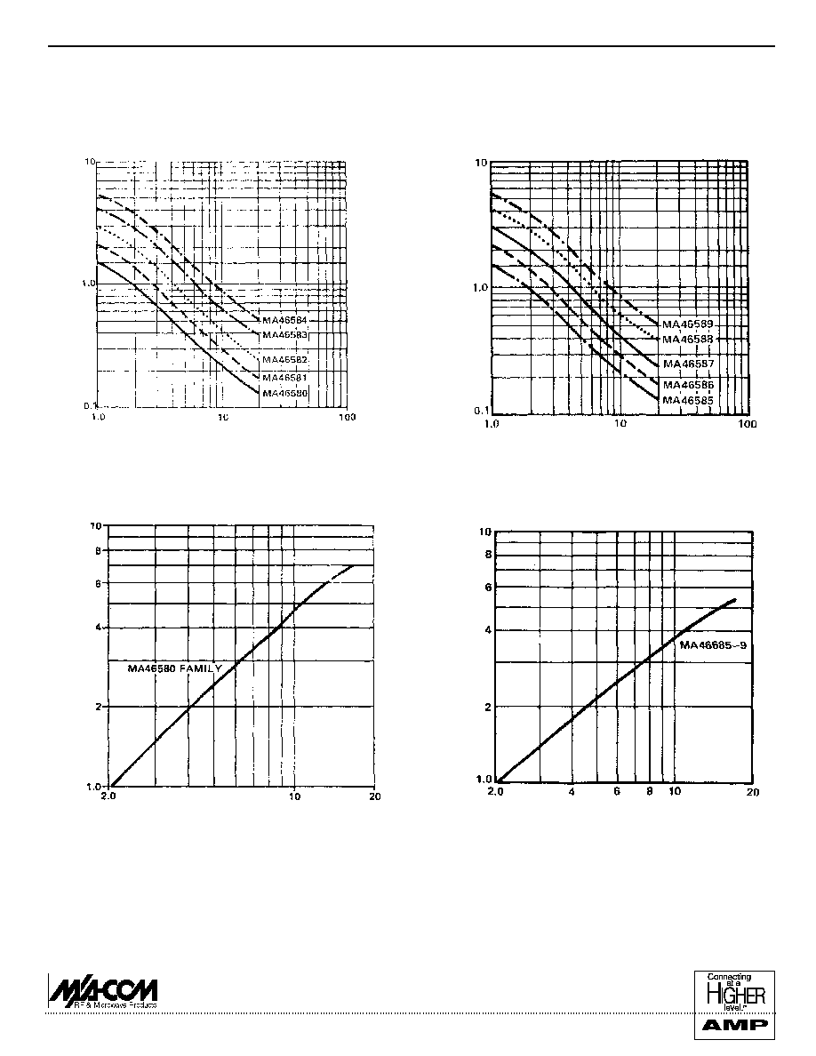
Typical Performance Curves (MA46580 Series)
Gamma = 1.0 ± 10% from 2-12 Volts (MA46585 through to MA46589)
Gamma = 1.25 ± 10% from 2-12 Volts (MA46580 through to MA46584)
REVERSE BIAS VOLTAGE (VOLTS)
CAPA
C
I
TANC
E
(pF
)
REVERSE BIAS VOLTAGE (VOLTS)
CAPA
C
I
TANC
E
(pF
)
MA46580 ≠ 46584 Capacitance vs Voltage
MA46585 ≠ 46589 Capacitance vs Voltage
REVERSE BIAS VOLTAGE (VOLTS)
CAPA
C
I
TANC
E
(pF
)
REVERSE BIAS VOLTAGE (VOLTS)
CAPA
C
I
TANC
E
(pF
)
Capacitance RatioC
T-2
/C
TV
for MA46580-46584 Series
Capacitance Ratio C
T-2
/C
TV
for MA46585-46589 Series


