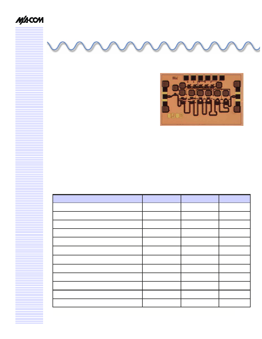
5-Bit Digital Attenuator
2.0-20.0 GHz
MAA
T
GM0004-DIE
2.0-20.0 GHz GaAs MMIC Attenuator
RO-P-DS-3052 - -
Preliminary Information
Features
5-Bit Attenuator, 23 dB Range, LSB = 0.75 dB
2.0 to 20.0 GHz Operation
TTL Control Inputs
Self-Aligned MSAG
Æ
MESFET Process
Primary Applications
VSAT
Point to Point Communications
Weather Radar
Military Radar
Electronic Warfare
Description
The
MAATGM0004-Die
is a 5-bit Digital Attenuator with
Parallel Input Control. This product is fully matched to 50
ohms on both the input and output.
Each device is 100% RF tested on wafer to ensure
performance compliance. The part is fabricated using
M/A-COM's repeatable, high performance and highly reli-
able GaAs Multifunction Self-Aligned Gate (MSAG
Æ
)
Electrical Characteristics: T
B
= 40∞C
1
, Z
0
= 50
, V
EE
= -5V
Parameter
Symbol
Typical
Units
Bandwidth f
2.0-20.0
GHz
Insertion Loss @ 10 GHz, Reference State
IL
4.0
dB
Input VSWR, All States
VSWR
1.4:1
Output VSWR, All States
VSWR
1.4:1
RMS Attenuation Error
RMS
< 1.0
dB
Attenuation Range
G 23 ∫
Current I
EE
5
mA
Input Third Order Intercept
ITOI
32
dBm
Input 1-dB Compression Point
P
1dB
26
dBm
Phase Variation over all Attenuation States @ 20 GHz
-13 to 21
∫
Insertion Loss @ 20 GHz, Reference State
IL
5.0
dB
RMS Attenuation Error, Calibrated
RMS
< 0.4
dB
RO-P-DS-3052 - -
2/7
2 to 20 GHz Digital Attenuator
MAATGM0004-DIE
V 1.00
Specifications subject to change without notice.
Customer Service: Tel. (888)-563-3949
Email: macom_adbu_ics@tycoelectronics.com
North America: Tel. (800) 366-2266
Asia/Pacific: Tel.+81-44-844-8296, Fax +81-44-844-8298
Europe: Tel. +44 (1344) 869 595, Fax+44 (1344) 300 020
Visit www.macom.com for additional data sheets and product information.
Maximum Operating Conditions
1
Operating Instructions
This device is static and light sensitive. Digital circuit
operation can be impaired under high intensity light,
e.g. microscope light. Please handle with care. To
operate the device, follow these steps.
1. Power Up: Apply V
EE
= -5 V.
2. Apply Logic Voltages to control Circuits as listed
in Recommended Operating Conditions
3.
Power Down: Set V
EE
= 0
Characteristic
Symbol
Min
Typ
Max
Unit
Source Voltage
V
EE
-5.2
-5 -4.8 V
Control Voltage
V
control pads
Logic High
3
5 5 V
Logic Low
0
0 0.4 V
Recommended Operating Conditions
Parameter
Symbol
Absolute Maximum
Units
Input Power
P
IN
31
dBm
Source Supply Voltage
V
EE
-6.0
V
Junction Temperature
T
j
180
∞C
Storage Temperature
T
STG
-55 to +150
∞C
1. Operation outside of these ranges may reduce product reliability. Operation at other than the typical values may
result in performance outside the guaranteed limits.
RO-P-DS-3052 - -
3/7
2 to 20 GHz Digital Attenuator
MAATGM0004-DIE
V 1.00
Specifications subject to change without notice.
Customer Service: Tel. (888)-563-3949
Email: macom_adbu_ics@tycoelectronics.com
North America: Tel. (800) 366-2266
Asia/Pacific: Tel.+81-44-844-8296, Fax +81-44-844-8298
Europe: Tel. +44 (1344) 869 595, Fax+44 (1344) 300 020
Visit www.macom.com for additional data sheets and product information.
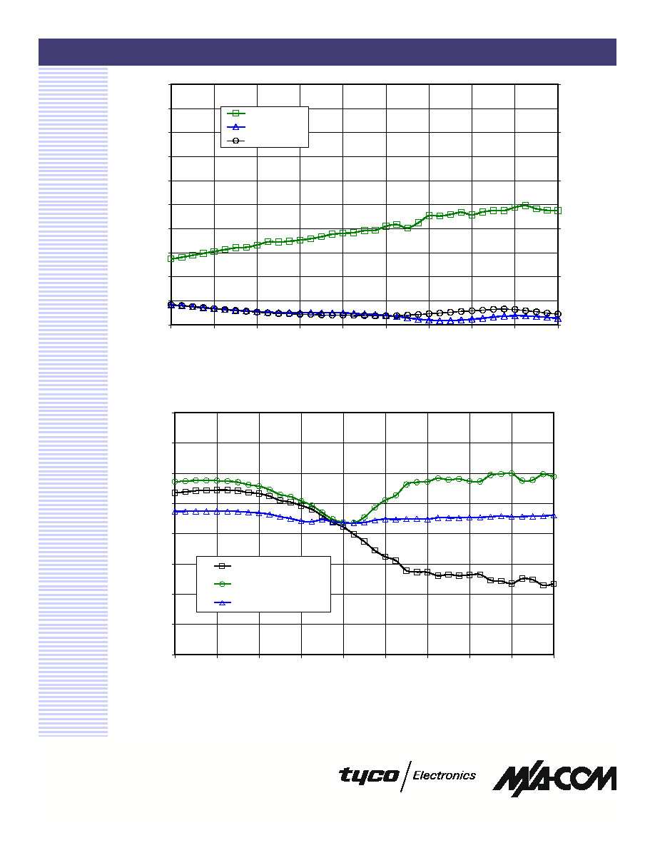
Figure 2. Attenuator Figures of Merit: Average Error vs Ref State, RMS Error
and Calibrated RMS Error over All States
Figure 1. Reference State Insertion Loss, Input and Output VSWR vs. Frequency
0
1
2
3
4
5
6
7
8
9
10
2
4
6
8
10
12
14
16
18
20
Frequency (GHz)
In
sertio
n
L
o
ss (d
B)
1
2
3
4
5
6
VSWR
Loss
Input VSWR
Output VSWR
-2.0
-1.5
-1.0
-0.5
0.0
0.5
1.0
1.5
2.0
2
4
6
8
10
12
14
16
18
20
Frequency (GHz)
Attenuator Error (dB)
Average Error
RMS Error
RMS Error, Calibrated
RO-P-DS-3052 - -
4/7
2 to 20 GHz Digital Attenuator
MAATGM0004-DIE
V 1.00
Specifications subject to change without notice.
Customer Service: Tel. (888)-563-3949
Email: macom_adbu_ics@tycoelectronics.com
North America: Tel. (800) 366-2266
Asia/Pacific: Tel.+81-44-844-8296, Fax +81-44-844-8298
Europe: Tel. +44 (1344) 869 595, Fax+44 (1344) 300 020
Visit www.macom.com for additional data sheets and product information.
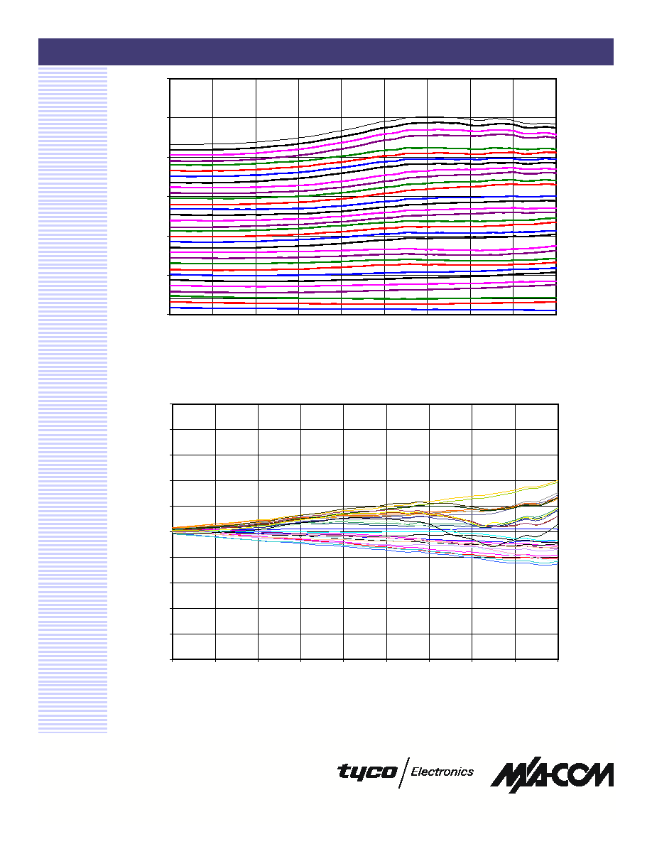
Figure 3. Insertion Loss vs Attenuator State
Figure 4. Relative Phase Change vs Attenuator State
0
5
10
15
20
25
30
2
4
6
8
10
12
14
16
18
20
Frequency (GHz)
Insertion Loss (dB)
-50
-40
-30
-20
-10
0
10
20
30
40
50
2
4
6
8
10
12
14
16
18
20
Frequency (GHz)
Relative P
hase (∫)
RO-P-DS-3052 - -
5/7
2 to 20 GHz Digital Attenuator
MAATGM0004-DIE
V 1.00
Specifications subject to change without notice.
Customer Service: Tel. (888)-563-3949
Email: macom_adbu_ics@tycoelectronics.com
North America: Tel. (800) 366-2266
Asia/Pacific: Tel.+81-44-844-8296, Fax +81-44-844-8298
Europe: Tel. +44 (1344) 869 595, Fax+44 (1344) 300 020
Visit www.macom.com for additional data sheets and product information.
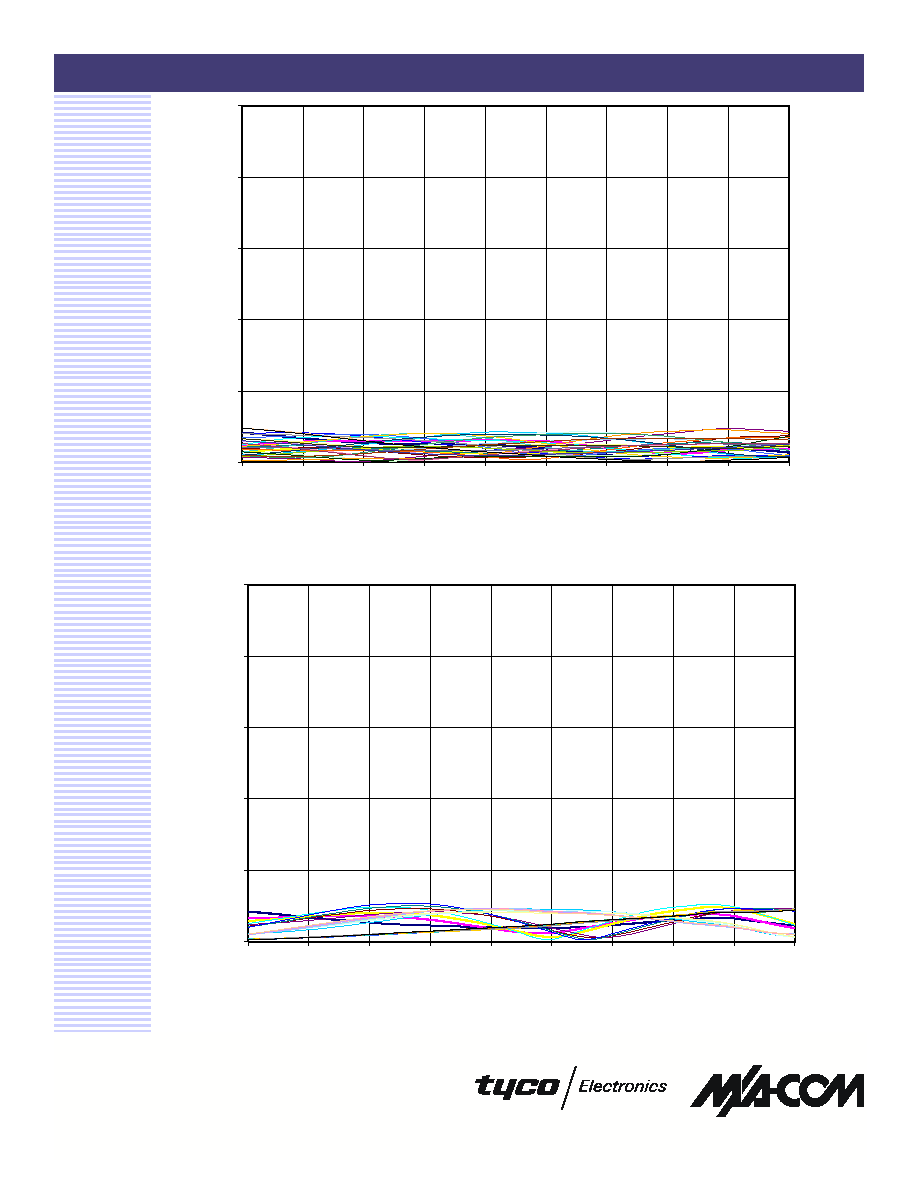
Figure 5. Input VSWR vs. Attenuator State
Figure 6. Output VSWR vs. Attenuator State
1
2
3
4
5
6
2
4
6
8
10
12
14
16
18
20
Frequency (GHz)
Input VSWR
1
2
3
4
5
6
2
4
6
8
10
12
14
16
18
20
Frequency (GHz)
Output VSWR


