 | ÐлекÑÑоннÑй компоненÑ: MDS-149 | СкаÑаÑÑ:  PDF PDF  ZIP ZIP |
Äîêóìåíòàöèÿ è îïèñàíèÿ www.docs.chipfind.ru
Double-Balanced Mixer,
10 - 1500 MHz
MD
-
/MDS
-
149
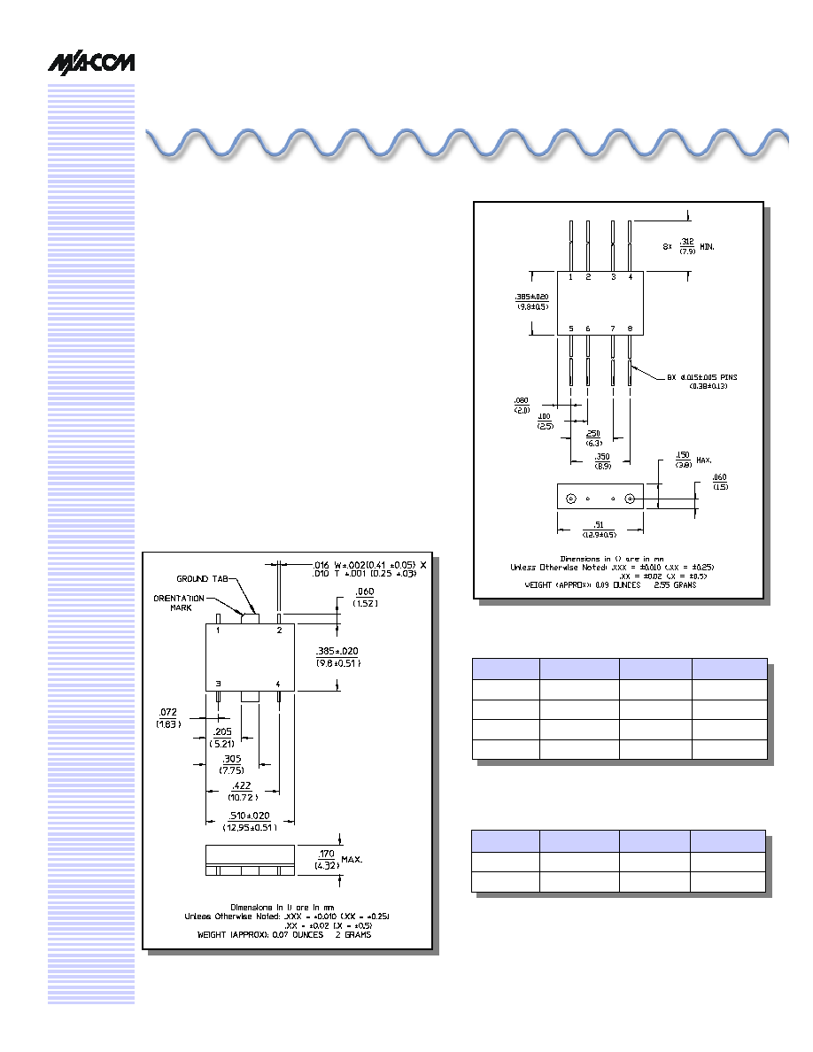
FP-2 (MD-149)
V 3.00
Features
n
Over Two-Decade Frequency Range
n
Conversion Loss: 6 dB Typical Midband
n
LO-RF Isolation: 40 dB Typical Midband
n
Fully Hermetic Package
n
Impedance: 50 Ohms Nominal
n
Maximum Input Power: 300 mW Max, Derated to 85°C
@ 3.2 mW/°C
n
IF Port Current: 50 mA Max.
n
MIL-STD-883 Screening Available
Description
Transformers convert the LO and RF paths to balanced
lines connecting to a low barrier, Schottky diode ring quad.
These transformers help provide excellent isolation between
ports. Conversion loss is low. The direct connection of the
IF port to the diode quad allows these mixers to be used as
phase detectors and bi-phase modulators.
SF-1 (MDS-149)
Pin Configuration (MD-149)
Pin No.
Function
Pin No.
Function
1
GND
5
LO
2
GND
6
GND
3
GND
7
GND
4
IF
8
RF
Pin Configuration (MDS-149)
Pin No.
Function
Pin No.
Function
1
GND
3
LO
2
IF
4
RF
Double Balanced Mixer, 10 - 1500 MHz
MD-/MDS-149
Specifications subject to change without notice.
n
North America: Tel. (800) 366-2266
n
Asia/Pacific: Tel.+81-44-844-8296, Fax +81-44-844-8298
n
Europe: Tel. +44 (1344) 869 595, Fax+44 (1344) 300 020
Visit www.macom.com for additional data sheets and product information.
V 3.00
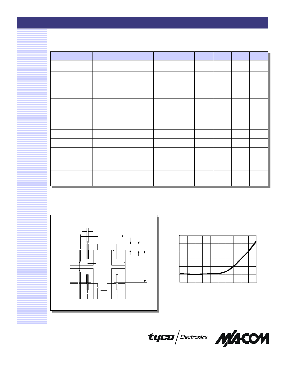
Typical Performance Curves
2
Conversion Loss (IF = 5 MHz,
RF = -5 dBm, LO = +7 dBm)
Electrical Specifications
1
: T
A
= -55°C to +85°C
Parameter
Test Conditions
Frequency
Units
Min
Typ
Max
Frequency Range
RF, LO Ports
IF Port
10 - 1500
DC - 1500
MHz
MHz
--
--
--
Conversion Loss
10 - 1000 MHz
1000 - 1500 MHz
dB
dB
--
--
--
--
7.5
10
Isolation
LO to RF
10 - 100 MHz
100 - 1000 MHz
1000 - 1500 MHz
dB
dB
dB
35
30
20
--
--
--
--
--
--
LO to IF
10 - 100 MHz
100 - 1000 MHz
1000 - 1500 MHz
dB
dB
dB
35
20
12
--
--
--
--
--
--
RF to IF
10 - 100 MHz
100 - 1000 MHz
1000 - 1500 MHz
dB
dB
dB
30
18
8
--
--
--
--
--
--
DC Polarity
Negative
--
--
--
--
--
DC Offset
--
--
mV
--
<4
--
RF Input
1 dB Compression
1 dB Desensitization
--
--
dBm
dBm
--
--
0
-2.0
--
--
SSB Noise Figure
Within 1 dB of Conversion Loss
Max
--
--
--
--
--
Typical Two-Tone IM
Ratio
with a 10 dBm input, each input,
25 MHz and 35 MHz IF
100 - 500 MHz
500 - 1000 MHz
1000 - 1500 MHz
dB
dB
dB
--
--
--
48
43
35
--
--
--
1. All specifications apply when operated at +7 dBm available LO power with 50 ohm source and load impedance.
5
6
7
8
9
10
11
10
20
50 100 200 500 1000
1400
1800
Frequency (MHz)
Conversion Loss (dB)
Bottom View of SF-1
.506
4X .016 ± .002
6X .050 (+.020/-.000)
4X .099 ± .010
.381
.000
.002
.165
.220
.385 Ref
.000 .002
.080
.143
.205
.305
.367
.430
.510 Ref
Double Balanced Mixer, 10 - 1500 MHz
MD-/MDS-149
Specifications subject to change without notice.
n
North America: Tel. (800) 366-2266
n
Asia/Pacific: Tel.+81-44-844-8296, Fax +81-44-844-8298
n
Europe: Tel. +44 (1344) 869 595, Fax+44 (1344) 300 020
Visit www.macom.com for additional data sheets and product information.
V 3.00
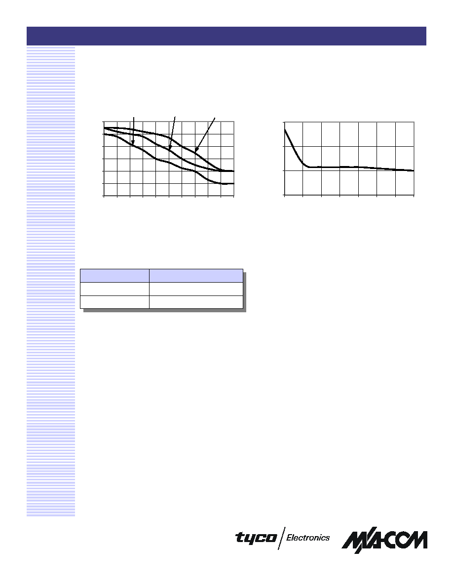
Typical Performance Curves
3
Conversion Loss vs. LO Power (RF =
1450 MHz, -10 dBm, LO = 1500 MHz)
Ordering Information
Part Number
Package
MD-149 PIN
FP-2
MDS-149 PIN
SF-1
7
8
9
10
0
2
4
6
8
10
12
LO Power (dBm)
Conversion Loss (dB)
Isolation
0
10
20
30
40
50
60
10
20
50
100 200 500 1000
1400
1800
Frequency (MHz)
Isolation (dB)
RF-IF
LO-IF
LO-RF