Radar Pulsed Power Module, 140W, 300
µ
s, 10% Duty
2.7 - 3.1 GHz
PHA2731-140L
V4.00
M/A-COM, Inc.
North America:
Tel. (800) 366-2266
s
Asia/Pacific: Tel. +81 (03) 3226-1671
s
Europe: Tel. +44 (1344) 869 595
Fax (800) 618-8883
Fax +81 (03) 3226-1451
Fax +44 (1344) 300 020
1
Specifications Subject to Change Without Notice.
Features
NPN Silicon Power Transistors
Input and Output Matched to 50
Duroid Circuit Board
Easily Combined For High Power Transmitters
Plated Copper Flange
q
q
q
q
q
Parameter
Symbol
Test Conditions
Units
Min.
Max.
Output Power
P
OUT
V
CC
=36 V, P
IN
=28 W, F=2.70, 2.90, 3.10 GHz
W
140
-
Power Gain
G
P
V
CC
=36 V, P
OUT
=140 W, F=2.70, 2.90, 3.10 GHz
dB
7
-
Collector Efficiency
C
V
CC
=36 V, P
OUT
=140 W, F=2.70, 2.90, 3.10 GHz
%
35
-
Input VSWR
VSWR
V
CC
=36 V, P
OUT
=140 W, F=2.70, 2.90, 3.10 GHz
-
-
2:1
Load VSWR Tolerance
VSWR-T
V
CC
=36 V, P
OUT
=140 W, F=2.70, 2.90, 3.10 GHz
-
-
2:1
Load VSWR for Stability
VSWR-S
V
CC
=36 V, P
OUT
=140 W, F=2.70, 2.90, 3.10 GHz
-
-
1.5:1
Pulse Droop
Dp
V
CC
=36 V, P
OUT
=140 W, F=2.70, 2.90, 3.10 GHz
dB
-
1
Electrical Characteristics
at 25∞C
Parameter
Absolute Maximum
Supply Voltage
40V
Input Power
35W
Output Power
200W
Thermal Resistance
0.8∞C/W
Power Dissipation
380W
Operating Case Temp.
-30 to +100∞C
Storage Temperature
-40 to +125∞C
1. Operation of this device outside any of these limits may cause
permanent damage.
Absolute Maximum Ratings
at 25∞C
1
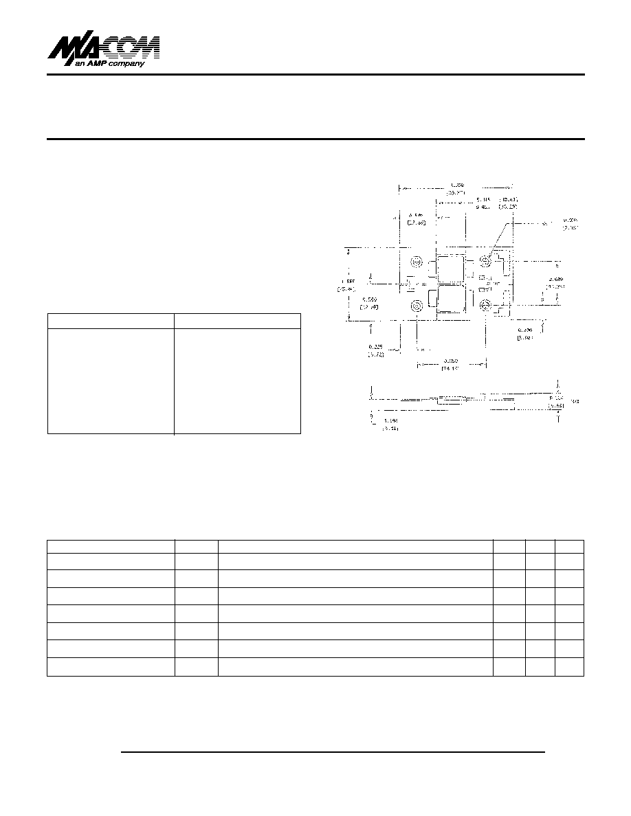
Unless Otherwise Noted, Tolerances Are:
Inches -0.005 (Millimeters -0.13mm)
