GaAs SPDT Reflective Switch
0.01 - 3 GHz
SW-137
M/A-COM, Inc.
North America:
Tel. (800) 366-2266
s
Asia/Pacific: Tel. +81 (03) 3226-1671
s
Europe: Tel. +44 (1344) 869 595
Fax (800) 618-8883
Fax +81 (03) 3226-1451
Fax +44 (1344) 300 020
1
Specifications Subject to Change Without Notice.
V2.00
Features
Isolation: 48dB Typ. at 1 GHz
High Intercept Point Over Wide Bandwidth
Trise, Tfall: 5 nS Typ.
DIP Package
Integral TTL Driver (CMOS Compatible)
50
Nominal Impedance
Description
M/A-COM's SW-137 is a GaAs MMIC SPDT reflective switch
with an integral Silicon ASIC driver. This device is in a 14-lead
DIP package. These switches offer high intercept points
over a wide bandwidth of operation, while maintaining low
DC power dissipation. These switches exhibit excellent per-
formance and repeatability from 0.01 to 3.0 GHz. The SW-137
is ideally suited for RF/IF communications applications.
Contact the factory for environmental screening.
Parameter
Test Conditions
Units
Minimum
Typical
Maximum
Reference Insertion Loss
.01 - 0.5 GHz
dB
0.9
.01 - 1.0 GHz
dB
1.0
.01 - 2.0 GHz
dB
1.4
.01 - 3.0 GHz
dB
1.6
Isolation
.01 - 0.5 GHz
dB
48
.01 - 1.0 GHz
dB
43
.01 - 2.0 GHz
dB
37
.01 - 3.0 GHz
dB
32
VSWR
.01 - 0.5 GHz
1.25:1
.01 - 1.0 GHz
1.4:1
.01 - 2.0 GHz
1.7:1
.01 - 3.0 GHz
2.0:1
Trise, Tfall
10% to 90%
nS
5
Ton, Toff
50% Control to 90%/10% RF
nS
22
Transients
In-band (peak-peak)
mV
45
1 dB Compression
0.01 - 3.0 GHz
dBm
+25
Input IP3
For two-tone input power
.01 - 3.0 GHz
dBm
+46
up to +5 dBm
Input IP2
For two-tone input power
.01 - 3.0 GHz
dBm
+76
up to +5 dBm
V
CC
V
+9
+12
+15
V
EE
V
-15
-12
-9
I
CC
V
CC
= +9 to +15 V
mA
20.0
I
EE
V
EE
= -9 to -15 V
mA
15.0
Vctl
Low
V
0.0
0.8
Vctl
High
V
2.0
5.0
Input Leakage Current (Low)
0 to 0.8 V
µA
1.0
Input Leakage Current (High)
2.0 to 5.0 V
µA
1.0
1. All specifications apply when operated with bias voltages of 9 to 15V for V
CC
and -9 to -15V for V
EE
and 50
impedance at all RF ports unless otherwise specified.
Electrical Specifications
1
,
T
A
= -55∞C to +85∞C
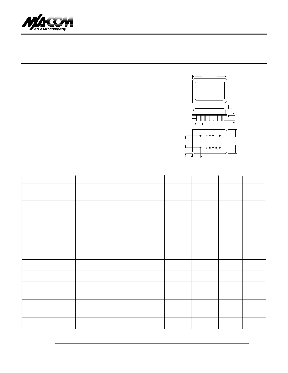
0.300
(7.6)
0.50
(12.7
0.5)
0.13
(3.3 0.5)
0.10
(2.5 0.5)
0.200
(5.1) MAX
0.120
(3.0) MIN
0.100
(2.5) TYP
0.018
±
0.005
(0.46
±
0.13) DIA.
14 PINS
0.87
(22.1
0.5)
CTL
RF 1
≠
+
RF 2
DI-1
q
q
q
q
q
q
Dimensions in () are in mm.
Unless Otherwise Noted: .xxx = ±0.010
(.xx = ±0.25)

GaAs SPDT Reflective Switch
SW-137
V2.00
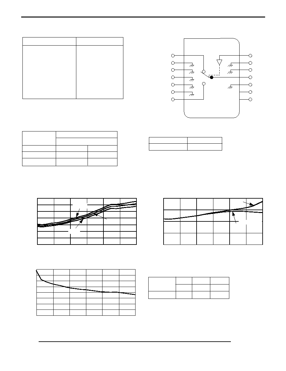
Functional Schematic (Top View)
Parameter
Absolute Maximum
Max. Input Power
0.05 GHz
+27 dBm
0.5 - 3.0 GHz
+34 dBm
Supply Voltages
V
CC
-0.5V to +16.5V
V
EE
-16.5V to +0.5V
Control Voltage
-0.5V to V
CC
+0.5V
Operating Temperature
-55∞C to +125∞
Storage Temperature
-65∞C to +150∞C
Absolute Maximum Ratings
1
1. Operation of this device above any one of these parameters
may cause permanent damage.
Typical Performance
INSERTION LOSS vs FREQUENCY
VSWR vs FREQUENCY
ISOLATION vs FREQUENCY
INSERTION LOSS (dB)
+85∞C
+25∞C
-55∞C
RFC
RF1, RF2
ISOLATION
(dB)
0.0
0.5
1.0
1.5
2.0
2.5
3.0
0.0
0.5
1.0
1.5
2.0
2.5
3.0
2.0
1.5
1.0
0.5
0.0
80
70
60
50
40
30
20
10
0
1.4
1.2
1.0
0.8
0.6
0.4
0.2
0.0
VSWR
FREQUENCY (GHz)
FREQUENCY (GHz)
0.0
0.5
1.0
1.5
2.0
2.5
3.0
FREQUENCY (GHz)
Ordering Information
2
Part No.
Package
SW-137 PIN
Dual Inline
2. Contact the factory for standard or custom
screening requirements
Truth Table
Condition of Switch
Control Inputs
RF Common to Each RF Port
C1
RF1
RF2
Low
On
Off
High
Off
On
C
1
GND
GND
RFC
GND
-VDC
+VDC
RF1
GND
GND
GND
GND
GND
RF2
Current (mA)
±9 V
±12 V
±15 V
V
CC
8
11
15
V
EE
4
7
9
M/A-COM, Inc.
North America:
Tel. (800) 366-2266
s
Asia/Pacific: Tel. +81 (03) 3226-1671
s
Europe: Tel. +44 (1344) 869 595
Fax (800) 618-8883
Fax +81 (03) 3226-1451
Fax +44 (1344) 300 020
2
Specifications Subject to Change Without Notice.

