GaAs SPDT RF Switch
DC - 3 GHz
SW-219
Features
Fast Switching Speed, 6 ns Typical
Ultra Low DC Power Consumption
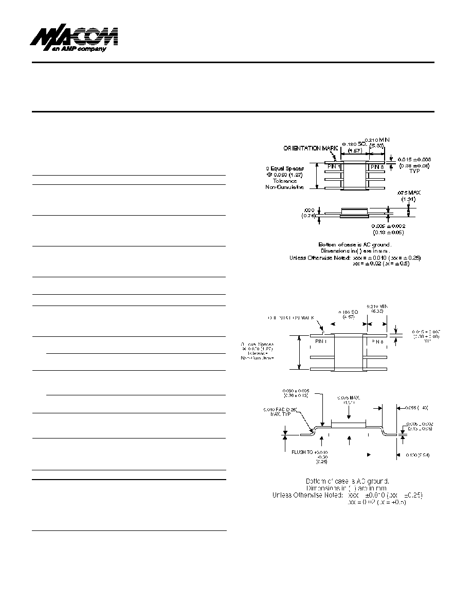
Small Package Size, 0.180" (4.6mm) Sq.
Guaranteed Specifications
1
(-55∞Cto +85∞C)
Frequency Range
DC ≠ 3.0 GHz
Insertion Loss
DC ≠ 3.0 GHz
0.9 dB Max
DC ≠ 2.0 GHz
0.8 dB Max
DC ≠ 1.0 GHz
0.8 dB Max
DC ≠ 0.5 GHz
0.7 dB Max
VSWR
DC ≠ 3.0 GHz
1.6:1 Max
DC ≠ 2.0 GHz
1.3:1 Max
DC ≠ 1.0 GHz
1.2:1 Max
DC ≠ 0.5 GHz
1.2:1 Max
Isolation
DC ≠ 3.0 GHz
23 dB Min
DC ≠ 2.0 GHz
28 dB Min
DC ≠ 1.0 GHz
38 dB Min
DC ≠ 0.5 GHz
43 dB Min
Operating Characteristics
Impedance
50 Ohms Nominal
Switching Characteristics
Trise, Tfall
3 ns Typ
Ton, Toff (50% CTL to 90%/10% RF)
6 ns Typ
Transients (In-Band)
10 mV Typ
Input Power for 1 dB Compression
Control Voltages (Vdc)
0/-5
0/-8
0.5 ≠ 3.0 GHz
+27
+33
dBm Typ
0.05 GHz
+21
+26
dBm Typ
Intermodulation Intercept Pt.
(for two-tone input power up to +13 dBm)
Intercept Points
IP2
IP3
0.5 ≠ 3.0 GHz
+62
+40
dBm Typ
0.05 GHz
+68
+46
dBm Typ
Control Voltages (Complementary Logic)
Vin Low
0 to -0.2V @ 20 µA Max
Vin High
-5V @ 50 µA Typ to -8V @ 300 µA Max
1. All specifications apply with 50 ohm impedance connected to all RF ports
with 0 and -5 Vdc control voltages.
2. See Appendix for MIL-STD-883 screening option.
CR-3
CR-10
Ordering Information
Part Number
Package
SW-219 PIN
Ceramic (CR-3)
SW-219G PIN
Ceramic Gull Winged
(CR-10)
SW-219B PIN
Screened to MIL-STD-883C,
Method 5008.4, Table VII
Class B Hybrid (CR-3)
q
q
q
V 2.00

V 2.00
GaAs SPDT RF Switch
SW-219
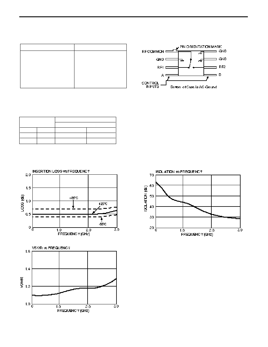
Typical Performance
Absolute Maximum Ratings
1
1.Operation of this device above any one of these parameters may cause
permanent damage.
Parameter
Absolute Maximum
Max. Input Power
0.05 GHz
+27 dBm
0.5≠2.0 GHz
+34 dBm
Control Voltage
+5 V, ≠8.5 V
Operating Temperature
≠55∞C to +125∞C
Storage Temperature
≠65∞C to +150∞C
Functional Schematic
Control Input
Condition of Switch
RF Common to each RF Por t
A
B
RF1
RF2
High
Low
ON
OFF
Low
High
OFF
ON
Truth Table
When an RF output is off, it is shorted to ground.

