GaAs SPDT High Isolation Terminated Switch, 0.5 - 2.0 GHz SW-394
V3.00
North America: Tel. (800) 366-2266, Fax (800) 618-8883
Asia/Pacific: Tel.+81-44-844-8296, Fax +81-44-844-8298
Europe: Tel. +44 (1344) 869 595, Fax+44 (1344) 300 020
Specifications subject to change without notice.
Visit www.macom.com for additional data sheets and product information.
Features
∑
Terminated RF Output
∑
High Isolation: 35 dB upto 2 GHz
∑
Positive Control
∑
Nanosecond Switching Speed
∑
CMOS Compatible Logic
∑
Low Cost SOIC 8 Plastic Package
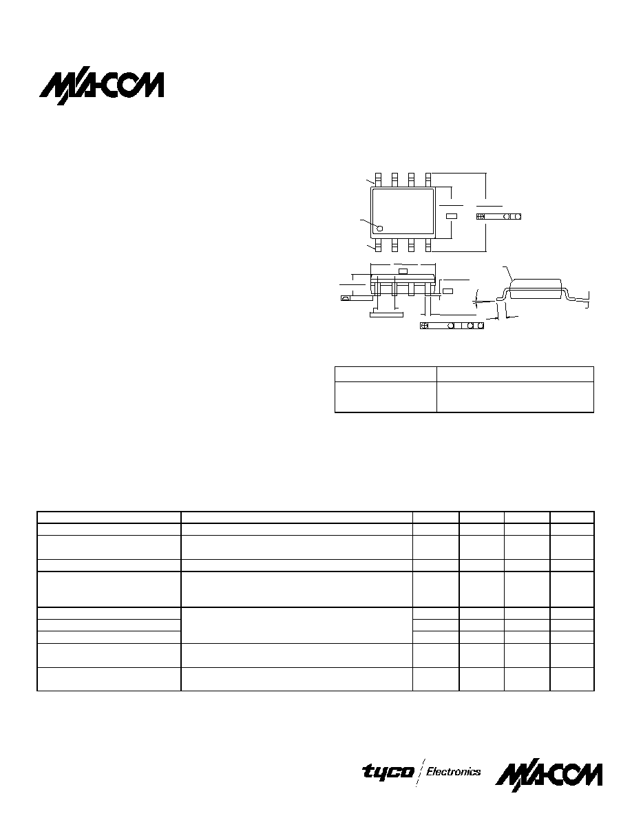
SOIC-8
1
Electrical Specifications: T
A
= +25∞C
1
=
=
=
=
GaAs SPDT High Isolation Terminated
Switch
SW-394
Parameter
Test Conditions
Units
Min.
Typ.
Max.
Insertion Loss
0.5 - 2.0 GHz
dB
1.3
1.5
Isolation
0.5 - 1.0 GHz
dB
37
40
1.0 - 2.0 GHz
dB
32
35
VSWR
0.5 - 1.5 GHz
1.6:1
1 dB Compression
Input Power, +5V Control/Supply 0.5 GHz
dBm
24
0.9 GHz
dBm
24
1.5 GHz
dBm
25
T
rise
, T
fall
10% to 90% RF, 90% to 10% RF
µ
s
34
T
on
, T
off
50% Control to 90% RF, Control to 10% RF
µ
s
36
Transients
In-band
mV
22
Input IP
2
2-Tone, 5 MHz spacing, 0.5 GHz
dBm
67
+10 dBm each
0.9 GHz
dBm
72
Input IP
3
2-Tone, 5 MHz spacing, 0.5 GHz
dBm
47
+10 dBm each 0.9 GHz
dBm
47
Description
M/A-COM's SW-394 is a GaAs monolithic SPDT terminated
switch in a low cost SOIC 8-lead plastic package. The SW-394
is ideally suited for use where low power consumption and high
isolation are required. Typical applications include transmit/
receive switching, switch matrices and switched filter banks in
systems such as radio and cellular equipment.
The SW-394 is fabricated using a mature 1-micron gate length
GaAs MESFET process. The process features full chip
passivation for increased performance and reliability.
Ordering Information
Part Number
Package
SW-394 PIN
SOIC 8-Lead Plastic Package
SW-394TR
Tape and Reel
1
1. Refer to Application Note M513 for reel size information.
1. All measurements taken at 900 MHz in a 50
system unless otherwise specified. Loss varies at 0.003 dB/∞C.
(.19/.25)
CHAMFER
(OPTIONAL)
(0.40/1.27)
.016/.050
0∞/8∞
-B-
BSC.
-C-
-A-
.010(.25)
C A
B
M
M
S
.050(1.27)
Orientation
Mark
.1497/.1574
(3.80/4.00)
M
M B
.010(.25)
.2284/.2440
(5.80/6.20)
.0532/.0688
(1.35/1.75)
.004(0.10)
.0075/.0098
PIN 8
PIN 1
.013/.020 (8 PL)
(.33/.51)
.0040/.0098
(.10/.25)
.1890/.1968
(4.80/5.00)
1. Dimensions are in: inches/mm
GaAs SPDT High Isolation Terminated Switch, 0.5 - 2.0 GHz SW-394
V3.00
North America: Tel. (800) 366-2266, Fax (800) 618-8883
Asia/Pacific: Tel.+81-44-844-8296, Fax +81-44-844-8298
Europe: Tel. +44 (1344) 869 595, Fax+44 (1344) 300 020
Specifications subject to change without notice.
Visit www.macom.com for additional data sheets and product information.
1
1.2
1.4
1.6
1.8
2
2.2
2.4
2.6
2.8
3
0.5
1
1.5
2
2.5
3
FREQUENCY (GHz)
VSWR
INPUT
OUTPUT INSERTION
OUTPUT ISOLATION
0
5
10
15
20
25
30
35
40
45
50
0.5
1
1.5
2
2.5
3
FREQUENCY (GHz)
I
S
O
L
AT
I
O
N (
d
B)
0
1
2
3
4
5
6
0.5
1
1.5
2
2.5
3
FREQUENCY (GHz)
I
N
SER
T
I
ON
L
O
SS (d
B
)
Parameter
Absolute Maximum
Input Power
+34 dBm
Operating Voltage(V
S
, V
A
, V
B
)
+8.5 Volts
Operating Temperature
-40∞C to +85∞C
Storage Temperature
-65∞C to +150∞C
Absolute Maximum Ratings
1
1. Exceeding any one or a combination of these limits may cause
permanent damage.
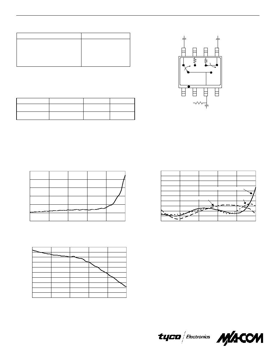
Typical Performance Curves
Insertion Loss vs. Frequency
VSWR vs. Frequency
Isolation vs Frequency
Functional Schematic
1
Control Input A Control Input B
RFC - RF2
RFC - RF1
0
1
Off
On
1
0
On
Off
Truth Table
"0" = ±0.2 Vdc
"1" = +5±0.2 Vdc
Vs = +5±0.2 Vdc
30
µ
A max. current total
1. Blocking capacitors are required on all RF ports. V
S
can be
applied at any RF port using 10K or greater pull-up resistor.
8
7
6
5
1
3
2
4
RF2 GND GND RF1
A
GND RFC
B
Vs
10k
50
=
=
=
=
50
=
=
=
=