Features
n
Positive Voltage Control (0 / +5 V)
n
High Isolation (53 dB typ. @ 0.9 GHz,
50 dB typ @ 1.9 GHz)
n
50-Ohm Internal Terminations
n
Low Insertion Loss (0.6 dB typ. @ 0.9 GHz,
0.7 dB typ. @ 1.9 GHz)
n
4 mm FQFP-N 16-Lead Package
Description
The M/A-COM SW-475 GaAs monolithic switch provides
high isolation in a low-cost, plastic surface mount package.
The SW -475 is ideal for applications across a broad range
of frequencies including synthesizer switching, transmit /
receive switching, switch matrices and filter banks in
systems such as radio and cellular equipment, PCS, GPS,
and fiber optic modules.
M/A-COM fabricates the SW-475 using an 0.5-micron gate
length MESFET process. The process features full chip
passivation for performance and reliability.
SW
-
475
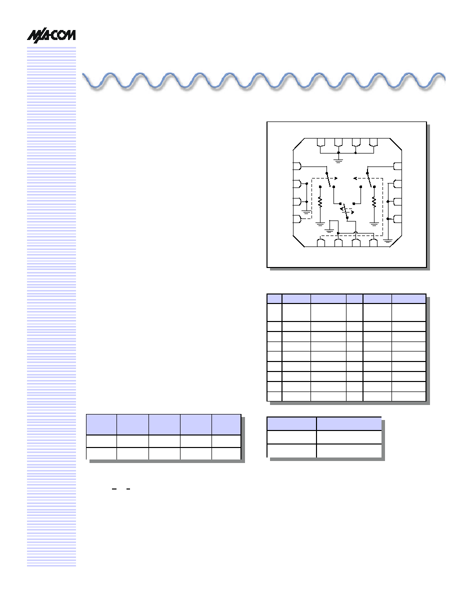
Functional Schematic
Handling Procedures
The following precautions should be observed to avoid
damage:
Static Sensitivity
Gallium arsenide integrated circuits are ESD sensitive and
can be damaged by static electricity. Use proper ESD
precautions when handling these devices.
Truth Table
Pin Function Description Pin Function Description
--
--
--
17
(pad)
GND
RF ground
1
RF2
RF port
16
GND
RF ground
2
GND
RF ground 15
GND
RF ground
3
GND
RF ground 14
GND
RF ground
4
V1
Control 1
13
GND
RF ground
5
V2
Control 2
12
RF1
RF port
6
GND
RF ground 11
GND
RF ground
7
RFC
RF port
10
GND
RF ground
8
GND
RF ground
9
GND
RF ground
Mode
(Control)
V1
V2
RFC -
RF1
RFC -
RF2
Positive
1
0
1
ON
OFF
Negative
2
1
0
OFF
ON
1. External DC blocking capacitors required on all RF ports.
We recommend 47 pF.
2. 3.0 V < VC < 8.0 V.
SPDT High Isolation Terminated Switch
0.5 - 3.0 GHz
Logic Level
Voltage Level
V
LO
"0" =
0 � 0.2 V
V
HIGH
1" =
V
C
� 0.2 V
RFC
RF2
RF1
1
2
3
4
5
6
7
8
9
10
11
12
13
14
15
16
V1
V2
PIN Configuration

SPDT High Isolation, Terminated Switch, 0.5 - 3.0 GHz
SW-475
Specifications subject to change without notice.
n
North America: Tel. (800) 366-2266, Fax (800) 618-8883
n
Asia/Pacific: Tel.+81-44-844-8296, Fax +81-44-844-8298
n
Europe: Tel. +44 (1344) 869 595, Fax+44 (1344) 300 020
Visit www.macom.com for additional data sheets and product information.
V 1.00
2
Electrical Specifications:
T
A
= 25 �C, V
CTL
= 0, 5.0 V (unless otherwise specified)
Parameter
Test Conditions
Units
Min.
Typ.
Max.
Insertion Loss
0.5- 1 GHz
dB
0.6
0.7
1.0 - 2.0 GHz
dB
0.7
0.8
2.0 - 3.0 GHz
dB
0.75
0.9
Isolation
0.5 - 1 GHz
dB
51
54
1.0 - 2.0 GHz
dB
48
52
2.0 - 3.0 GHz
dB
45
50
Return Loss
0.5 - 1 GHz
dB
15
20
1.0 - 2.0 GHz
dB
15
20
2.0 - 3.0 GHz
dB
15
20
Input IP
2
2-Tone 900 MHz, 5 MHz spacing (V
C
= 5.0 V)
dBm
83
Input IP
3
2-Tone 900 MHz, 5 MHz spacing (V
C
= 5.0 V)
dBm
43
TRISE, TFALL
10% to 90% RF & 90% to 10% RF
nS
24
TON, TOFF
50% of V
C
to 10 % / 90% RF
nS
15
Transients
V
C
= 5.0 V square wave, in-band
mV
12
Absolute Maximum Ratings
1
Parameter
Absolute Maximum
Max Input Power (0.5 - 3.0 GHz)
3 V Control
+30 dBm
5 V Control
+33 dBm
Operating Voltage
+8.5 volts
Operating Temperature
-40 �C to +85 �C
Storage Temperature
-65 �C to +150 �C
1. Exceeding any one or combination of these limits may cause
permanent damage.
1. DC blocking capacitors requires on all RF ports.
SPDT High Isolation, Terminated Switch, 0.5 - 3.0 GHz
SW-475
Specifications subject to change without notice.
n
North America: Tel. (800) 366-2266, Fax (800) 618-8883
n
Asia/Pacific: Tel.+81-44-844-8296, Fax +81-44-844-8298
n
Europe: Tel. +44 (1344) 869 595, Fax+44 (1344) 300 020
Visit www.macom.com for additional data sheets and product information.
V 1.00
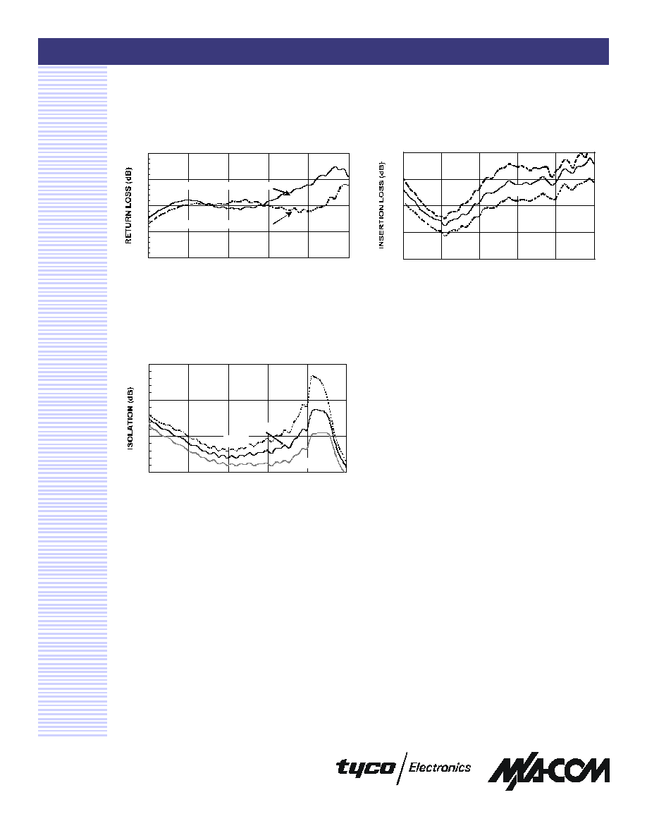
Typical Performance Curves
3
Isolation Vs. Frequency Over
Temperature
Return Loss Vs. Frequency
Insertion Loss Vs. Temperature
10
15
20
25
30
0.5
1.0
1.5
2.0
2.5
3.0
FREQUENCY (GHz)
INPUT RETURN LOSS ("ON" STATE)
OUTPUT RETURN LOSS ("OFF" STATE)
0.4
0.5
0.6
0.7
0.8
0.5
1.0
1.5
2.0
2.5
3.0
FREQUENCY (GHz)
+85 �C
+25 �C
-40 �C
50
55
60
65
0.5
1.0
1.5
2.0
2.5
3.0
FREQUENCY (GHz)
+85 �C
+25 �C
-40 �C
SPDT High Isolation, Terminated Switch, 0.5 - 3.0 GHz
SW-475
Specifications subject to change without notice.
n
North America: Tel. (800) 366-2266, Fax (800) 618-8883
n
Asia/Pacific: Tel.+81-44-844-8296, Fax +81-44-844-8298
n
Europe: Tel. +44 (1344) 869 595, Fax+44 (1344) 300 020
Visit www.macom.com for additional data sheets and product information.
V 1.00
Ordering Information
1. If you need a specific reel size, please consult the factory
for part number.
Part Number
Package
SW-475 PIN
4-mm FQFP-N 16-lead Plastic
Package
SW-475TR
Forward tape and reel
1
SW-475TR-3000
3000 tape and reel
1
SW-475SMB
Sample board
4
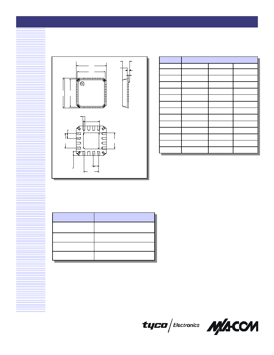
4-mm FQFP-N, 16-Lead (MLP)
Package
Note: See JEDEC MO-220A VGGC for additional dimen-
sional and tolerance information.
Dim
Measurement (mm)
Min.
Nom.
Max.
A
0.80
0.90
1.00
A1
0
0.02
0.05
A2
0.70
0.65
1.00
A3
0.20 ref.
b
0.23
0.28-
0.35
D
-
4.00 basic
-
D1
-
3.75 basic
-
E
-
4.00 basic
-
E1
-
3.75 basic
-
L
0.50 typ.
0.60 typ.
0.75 typ.
D2
0.75
1.70
2.25
e
0.65 basic
E2
0.75
1.70
2.25
E E1
D
D1
1
2
3
16
A
A2
A3
A1
e
4 x e
L
e
4 x e
E2
16 x b
D2