GaAs SPDT Switch, Absorptive,
Single Supply, DC - 4 GHz
SW90
-
0002
CSP-1
V 3.00
Electrical Specifications: T
A
= 25∞C
Parameter
Test Conditions
Frequency
Units
Min.
Typ.
Max.
Insertion Loss
RFC--RF1,RF2
(Logic per truth table)
DC - 4.0 GHz
dB
--
--
1.8
Isolation
RF1--RF2 (All Logic "0")
DC - 4.0 GHz
dB
30
--
--
VSWR
On (RFC,RF1, RF2)
(Logic per truth table)
DC - 4.0 GHz
Ratio
--
--
2.0:1
VSWR
Off (RF1, RF2)
(Logic per truth table)
DC - 4.0 GHz
Ratio
--
--
1.8:1
1 dB Compression
--
--
50 MHz
0.5 - 4.0 GHz
dBm
dBm
--
--
18
29
--
--
Input IP
3
Two-tone inputs up to +5 dBm
50 MHz
0.5 - 4.0 GHz
dBm
dBm
--
--
36
46
--
--
Switching Speed
Ton (50% Control to 10% RF)
nS
--
31
--
Toff (50% Control to 90% RF)
nS
--
19
--
Trise (10% to 90% RF)
nS
--
6
--
Tfall (90% to 10% RF)
nS
--
2
--
Vcc
--
--
V
4.5
5.0
5.5
Logic "0"
Sink Current is 20 µA max.
--
V
0.0
--
0.8
Logic "1"
Source Current is 20 µA max.
--
V
2.0
--
5.0
Icc
Vcc min to max, Logic "0" or "1"
--
mA
--
5
8
Features
n
Operates DC - 4 GHz on Single Supply
n
ASIC TTL / CMOS Driver
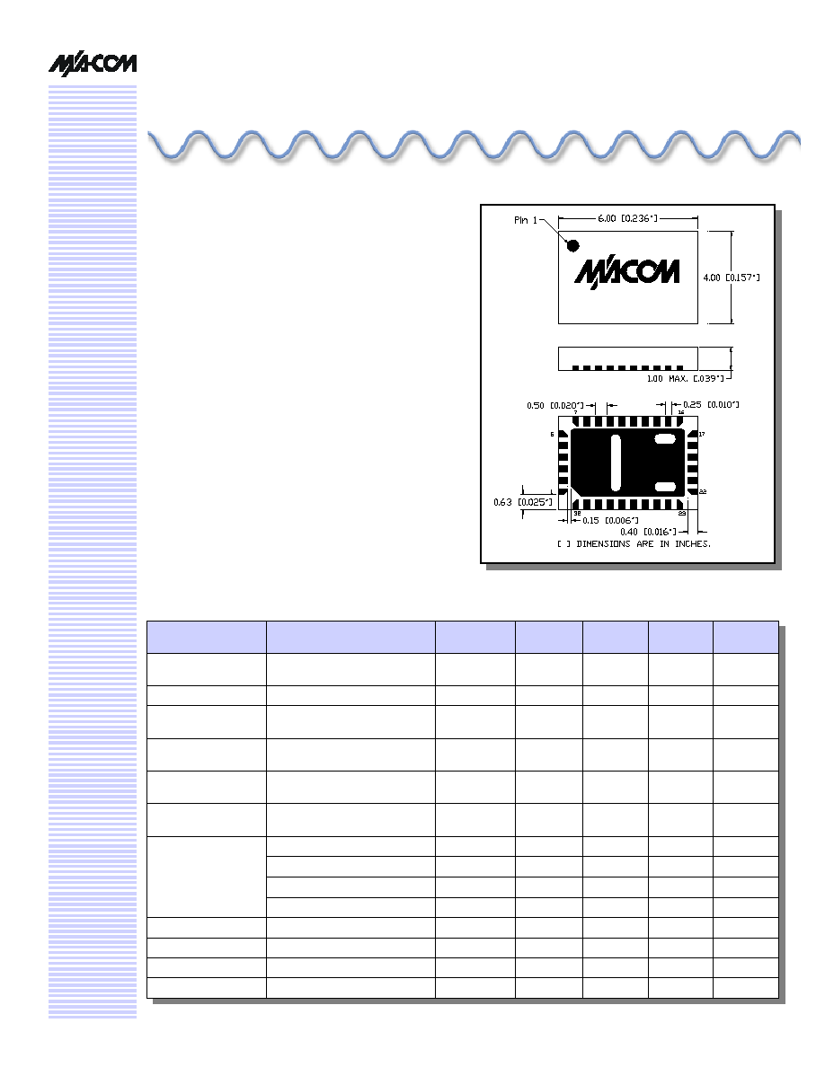
n
Leadless 4 x 6 mm Chip Scale Plastic Package
n
Low DC Power Consumption
n
50 Ohm Nominal Impedance
n
Test Boards are Available
n
Tape and Reel are Available
Description
M/A-COM's SW90-0002 is a SPDT absorptive pHEMT
switch with integral TTL driver. This device is in an MLP
plastic surface mount package. This switch offers excellent
broadband performance and repeatability from DC to 4
GHz, while maintaining low DC power dissipation. The
SW90-0002 is ideally suited for wireless infrastructure
applications.

GaAs SPDT Switch, Absorptive, Single Supply, DC - 4 GHz
SW90-0002
Specifications subject to change without notice.
n
North America: Tel. (800) 366-2266
n
Asia/Pacific: Tel.+81-44-844-8296, Fax +81-44-844-8298
n
Europe: Tel. +44 (1344) 869 595, Fax+44 (1344) 300 020
Visit www.macom.com for additional data sheets and product information.
V 3.00
2
Pin Configuration
1,2,3
Pin No.
Function
Pin No.
Function
1
NC
17
NC
2
GND
18
C1
3
RFC
19
NC
4
GND
20
V
CC
5
NC
21
NC
6
NC
22
NC
7
GND
23
CP1
8
RF1
24
CP2
9
GND
25
NC
10
NC
26
V
EE
11
NC
27
NC
12
V
EE
28
NC
13
NC
29
NC
14
V
CC
30
GND
15
NC
31
RF2
16
NC
32
GND
Parameter
Absolute Maximum
Max. Input Power
0.05 GHz
0.5 - 4.0 GHz
+27 dBm
+34 dBm
Bias Voltages
V
CC
Control Voltage
6
+5.5V
-0.5V to V
CC
+0.5V
Operating Temperature
-40∞C to +85∞C
Storage Temperature
-65∞C to +125∞C
Absolute Maximum Ratings
4,5
4. Operation of this device above any one of these
parameters may cause permanent damage.
5. When the RF input is applied to the terminated port, the
absolute maximum power is +30 dBm.
6. Standard CMOS TTL interface, latch-up will occur if logic
signal is applied prior to power supply.
Recommended PCB Layout
7
Functional Schematic
1. NC = No Connection
2. VEE is internally generated and must remain isolated from
external power supplies.
3. Connections and external components shown in functional
schematic are required. 0.1 µF Capacitors need to be
located near pins 20 & 26.
Truth Table
Control Input
Condition of the Switch
C1
RF1
RF2
0
Off
On
1
On
Off
RF Common to each RF Port
"0" = TTL Low "1" = TTL High
7. Application Note C2083 is available on line at
www.macom.com
GaAs SPDT Switch, Absorptive, Single Supply, DC - 4 GHz
SW90-0002
Specifications subject to change without notice.
n
North America: Tel. (800) 366-2266
n
Asia/Pacific: Tel.+81-44-844-8296, Fax +81-44-844-8298
n
Europe: Tel. +44 (1344) 869 595, Fax+44 (1344) 300 020
Visit www.macom.com for additional data sheets and product information.
V 3.00
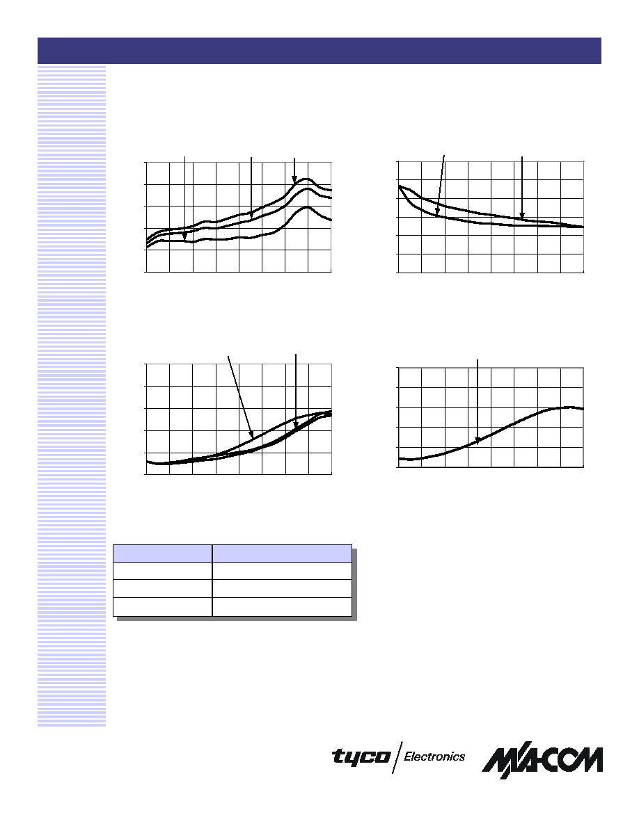
Typical Performance Curves
Isolation (dB) vs. Frequency
Insertion Loss vs. Frequency
On VSWR vs. Frequency
3
Ordering Information
Part Number
Package
SW90-0002
Bulk Packaging
SW90-0002TR
Tape and Reel (1K Reel)
SW90-0002-TB
Units Mounted on Test Board
VSWR (Terminations) vs. Frequency
0.0
0.4
0.8
1.2
1.6
2.0
0
1000
2000
3000
4000
Frequency (MHz)
Insertion Loss (dB)
+85∞C
- 40∞C
+25∞C
0
15
30
45
60
75
90
0
1000
2000
3000
4000
Frequency (MHz)
Isolation (dB)
Out-Out
RFC-RFn
1.00
1.20
1.40
1.60
1.80
2.00
0
1000
2000
3000
4000
Frequency (MHz)
VSWR
RF1, RF2
RFC
1.00
1.20
1.40
1.60
1.80
2.00
0
1000
2000
3000
4000
Frequency (MHz)
VSWR
RF1,RF2