 | –≠–ª–µ–∫—Ç—Ä–æ–Ω–Ω—ã–π –∫–æ–º–ø–æ–Ω–µ–Ω—Ç: AN884 | –°–∫–∞—á–∞—Ç—å:  PDF PDF  ZIP ZIP |

www.maxim-ic.com/an884 Page 1 of 6
SENSOR SIGNAL CONDITIONERS
Application Note 884: Dec 13, 2001
Miniature Flow Sensor Has Electronic Temperature Compensation
Fluid analysis is essential in a wide range of current applications. Biology, medical
analysis, genetic engineering, and many other fields rely on fast, precise, and
reproducible chemical and biological analyses. Tools that automate the dosing and
analysis of fluid samples are essential for affordable performance.
Highly specialized electronic sensors have been designed to automate sample analysis, but the
dosing of liquids ≠ still a prominent issue ≠ must be done physically. This operation is usually
accomplished with specialized micro-syringes driven by stepper motors. It's easy to imagine the
difficulty and expense associated with such setups.
In a novel approach to this problem, DASA IMT and Seyonic SA (both of Neuch‚tel,
Switzerland) developed flow-through micro-fluidic dosing as part of a toolkit for experiments
performed in space. As described in the following, a key element of that design was a micro-
flow sensor device. Requirements were:
∑
Small size
∑
Chemical inertia
∑
Temperature stability
∑
Long-term stability
∑
Simple, easy, and fully automated recalibration
∑
Linear voltage-versus-pressure output
One way to measure micro-fluidic flow is by measuring the pressure difference across a
restriction integrated into a micro-flow channel. Pressure measurements are performed with
dual piezo-resistive pressure sensors, one placed before the restriction and the other behind.
To insure that the sensor is not affected or altered by chemically aggressive fluids, the fluid
under pressure is applied to the back of the sensor diaphragm (whose monocrystal-line silicon
is relatively insensitive to the chemicals) rather than the front. This unusual configuration
protects sensitive microelectronic circuits on top of the sensor by shielding them from the
liquid. To prevent error from mechanical-tension forces, the sensor is mounted on a thick
ceramic substrate (Figure 1).
www.maxim-ic.com/an884 Page 2 of 6
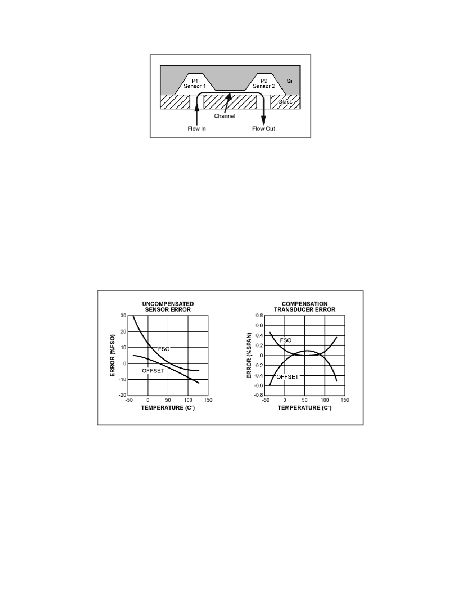
Figure 1. This cross section shows the dual piezo-resistive pressure sensors mounted
on a thick ceramic substrate.
Piezo-resistive pressure sensors exhibit excellent sensitivity and reproducibility, but they are
quite sensitive to changes in environmental temperature. Until recently, there was no way to
compensate these errors while achieving the small size and fast response needed in micro-
fluidic flow sensing. One solution to this problem is the new MAX1458 sensor-signal
processor, which compensates piezo-resistive sensors for initial and temperature-dependent
errors. Figure 2 compares the output of an uncorrected sensor with the same output
compensated with this IC.
Figure 2. This before-and-after comparison shows the reduction in sensor error
achieved with the MAX1458 sensor-signal conditioner.
Digital and user-programmable registers perform a fully electronic compensation of the analog
signal path. For applications exposed to large environmental temperature changes such as the -
40∞C to +125∞C automotive range, the MAX1458 delivers a total output accuracy better than
1%. For a more limited span such as +15∞C to +45∞C, the total pressure accuracy approaches
0.1%.
www.maxim-ic.com/an884 Page 3 of 6
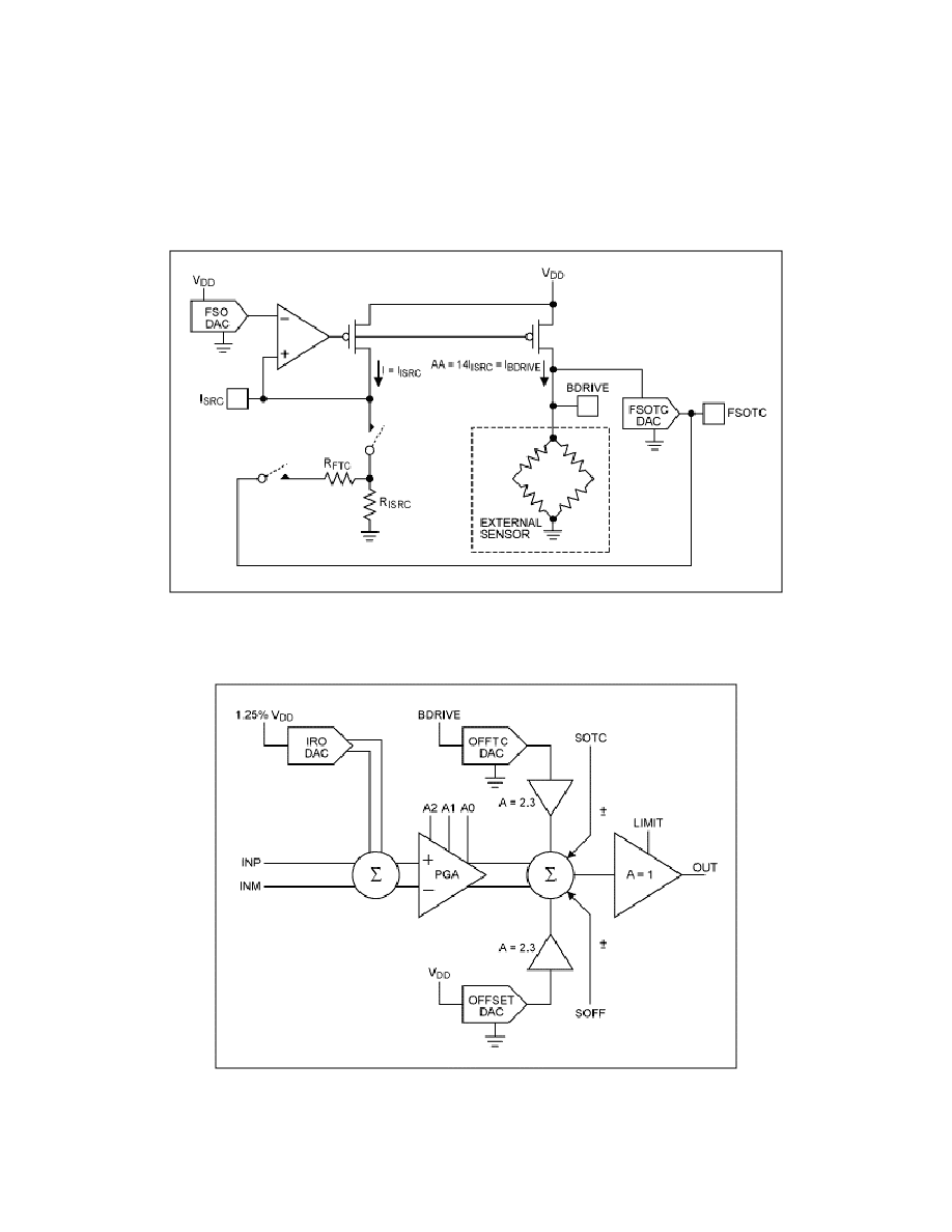
A block diagram illustrates the IC's internal structure (Figure 3a and 3b). A patented sensor-
bridge excitation circuit counteracts any decrease in sensitivity by causing the bridge-drive
voltage to rise with temperature. The compensated sensor bridge also acts as a temperature
sensor, and is sufficiently linear to serve for correcting offset drift vs. temperature.
Figure 3a. Patented sensor-bridge excitation circuit
Figure 3b. A differential analog-output path

www.maxim-ic.com/an884 Page 4 of 6
The output signal is adjustable between 0.5V and 4.5V (when operating with 5V supplies), and
it accommodates sensor sensitivities of 10mV/V and higher. All coefficients required for
compensation are held in an EEPROM internal to the MAX1458. Thus, the setup is easily and
automatically calibrated via a simple 4-wire serial interface.
Because the relationship between measured differential pressure and liquid flow rate depends
on the liquid's viscosity, which in turn changes with temperature, the MAX1458 provides a
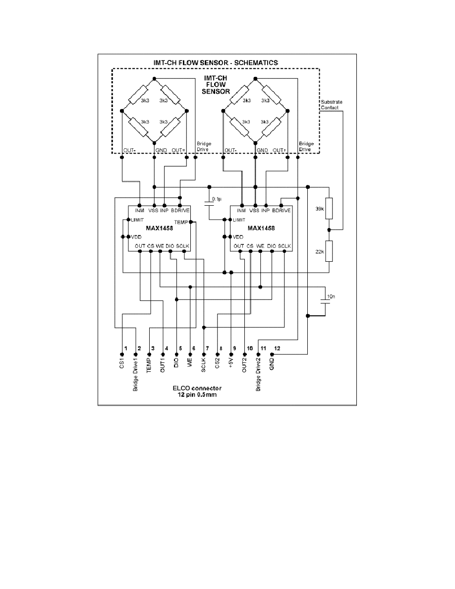
temperature output signal for use in external signal processing. This setup (Figure 4) allows the
measurement of flow rates no higher than 5.5µl/sec. The analog pressure signals, the
temperature sensor terminals, and all other connections are made accessible at a connector for
external post?processing.
www.maxim-ic.com/an884 Page 5 of 6
Figure 4. The pressure-sensor module consists of a dual flow sensor and two signal-
conditioner ICs.
A photo of the 12x19mm pressure-sensing module (Figure 5) illustrates the MCM technology:
a monolithic flow sensor module, wire-bonded to the ceramic carrier, connects to the two
sensor-signal processors (MAX1458s), which are also wire-bonded and mounted as dice.
Figure 6 illustrates a micro-fluidic dosing and analysis system, in which the flow-sensor output
described above serves as a feedback signal in achieving continuous and dynamic flow-rate
control.