 | –≠–ª–µ–∫—Ç—Ä–æ–Ω–Ω—ã–π –∫–æ–º–ø–æ–Ω–µ–Ω—Ç: DS2740K | –°–∫–∞—á–∞—Ç—å:  PDF PDF  ZIP ZIP |

1 of 9
040803
FEATURES
ß Demonstrates the Capabilities of the DS2740
High-Precision Coulomb Counting IC
Including:
- Real-Time Current Measurements
- High-Precision Current Accumulation
- Identification
- Programmable I/O Operation
ß Interfaces to the Serial Port of a PC Running
Windows 95 or Newer
INDEX
Evaluation Kit Contents
Equipment Needed
Introduction
Setup and Installation
Board Connections
Software Installation
Selecting the COM Port
Program Menus
Program Tabs
Meters
Tab
Data Log Tab
Memory
Tab
Pack Information Tab
EVALUATION KIT CONTENTS
1 pc. TSSOP Evaluation Board
1 pc. DS9123 Serial Port Adapter
1 pc. RJ-11 Phone Cable
1 pc. DS2740K CD containing:
DS2740K Evaluation Software
DS2740 Related Documentation
EQUIPMENT NEEDED
1) A PC running Windows 95 or newer with a
CD-ROM drive and an available serial port.
2) Cables with mini-grabber style clips or the
ability to solder directly to connection pads.
3) A Lithium-Ion (Li+) battery or 3-cell NiMH
stack and a power supply and/or load circuit.
INTRODUCTION
The DS2740K evaluation kit makes performance evaluation, software development, and prototyping with
the DS2740 high-precision coulomb counting IC easy. The evaluation board interfaces to a PC running
Windows 95 or newer through a DS9123 serial port adapter and RJ-11 cable connection. The CD-ROM
provided contains all related data sheets along with the evaluation software.
The DS2740K evaluation software gives the user complete control of all functions of the DS2740.
Separate control tabs allow the user access to all memory locations, all status registers, and real-time
updates of all monitored parameters. The software also incorporates a data-logging feature to monitor a
battery over time.
The evaluation board circuit is designed to provide the DS2740 with accurate parameter measurements
and protect the DS2740 from ESD damage.
*Kit demonstration boards will vary as they are improved upon over time. For information on the
demonstration board circuits refer to the documentation directory on the DS2740K CD-ROM.
DS2740K
High-Precision Coulomb Counter IC
Evaluation Kit
www.maxim-ic.com
PD122402*
DS2740K TSSOP

DS2740K
2 of 9
SETUP AND INSTALLATION
Board Connections
Connections to the demonstration board are best made either by soldering directly to the pads or by using
cables with mini-grabber clips. Communication to the board can be accomplished by connecting the RJ-
11 jack to the DS9123 serial port adapter with the 2 conductor cable provided. Then the DQ and PAC-
terminals on the RJ-11 jack can be wired directly to the DQ and PAC- pads on the demonstration board.
Figure 1 shows the recommended circuit for the DS2740K demonstration board. The Li+ cell or NiMH
cell stack is connected between the BAT+ and BAT- pads. If a Li+ cell is used a protection circuit must
be included between the battery and the demo board. The user system load circuit/charger is connected
from BAT+ to PAC-. The evaluation software can be run with or without a load or charger as long as a
cell is connected between the BAT+ and BAT- terminals providing a minimum of 2.7V to power the
DS2740.
Figure 1. PD122402 Cell, Load, and Charger Connections
Software Installation
To install the DS2740K software, exit all programs currently running and insert the DS2740K software
CD into your computer's CD-ROM drive. Run SETUP.EXE from the setup directory and the installation
process begins. Follow the prompts to complete the installation. The DS2740K software can be
uninstalled in the Add/Remove Programs tool in the Control Panel. After the installation is complete,
open the DS2740K folder and run DS2740K.EXE or select DS2740K from the program menu. A splash
screen containing information about the evaluation kit appears as the program is being loaded.
The documentation directory also located on the CD contains all relevant data sheets and application
notes on the DS2740 and DS2740K. They are stored in Adobe Acrobat format for easy viewing and can
also be accessed through the help menu after the program starts.
Selecting the COM Port
BATTERY
+
-
Load
Circuit/
Charger
DS2740K EVALUATION BOARD
B+
DQ
B-
PIO
P-
Li-Ion
Protection
Circuit
DQ
P-
RJ-11 Jack
DS2740K
3 of 9
The first time the software runs, the Serial Port Settings window appears. In this window, select the COM
port to which the DS9123 is attached and the desired communication rate, then hit OK. The DS2740K
software saves this COM port selection and automatically uses the selection each time the program starts.
To change the COM port later, click the Preferences option on the menu bar, select Serial Port Settings,
and then select the appropriate port. To attempt to automatically locate the DS9123, click the Poll Serial
Ports button. Warning: automatically polling for the DS9123 can disrupt other devices connected to your
computer's COM ports.
PROGRAM MENUS
Several pull-down menu options have been provided to simplify use of the DS2740K software for the
user. Their functions are individually detailed below.
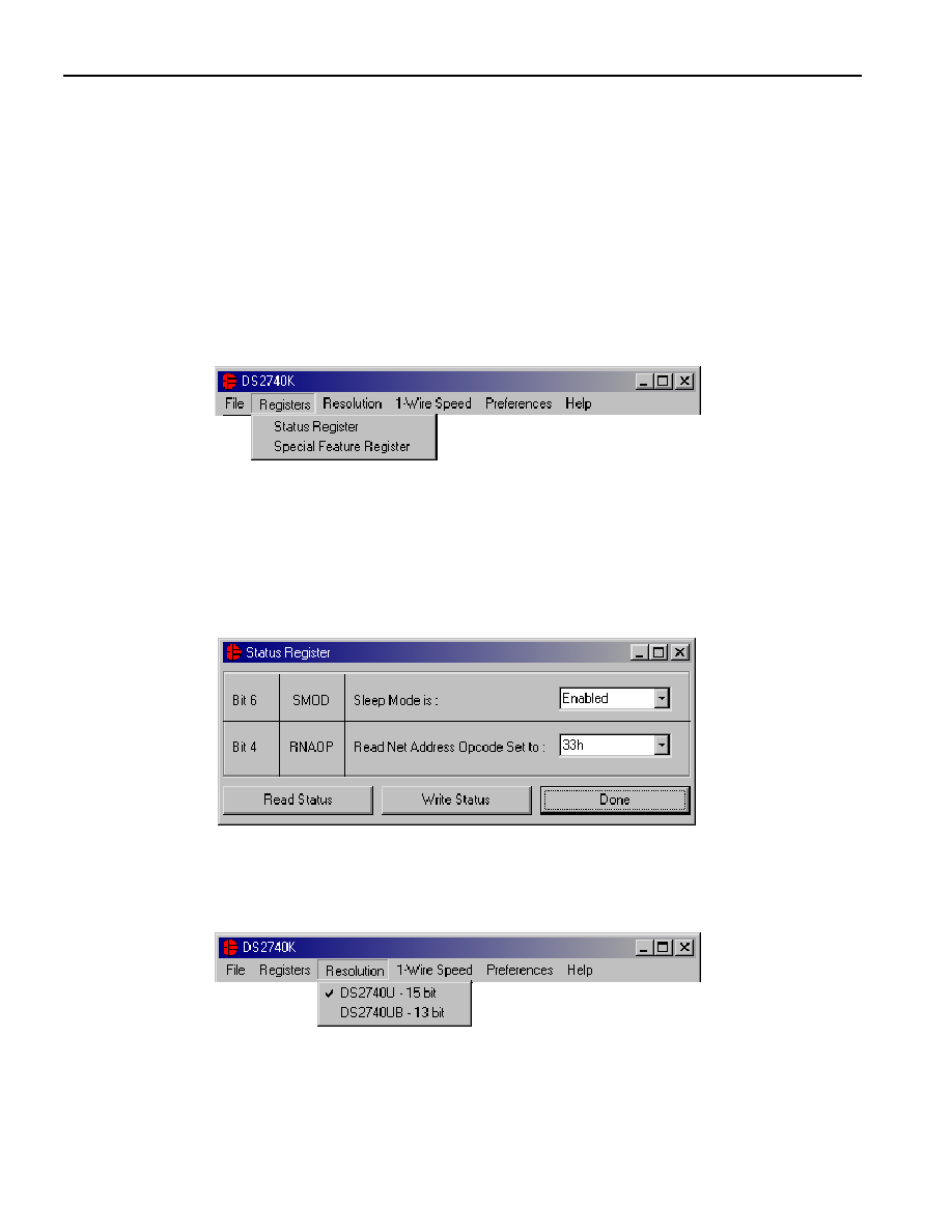
Registers Menu
The Registers Menu gives immediate access to the Status and Special Feature Registers in the DS2740.
Selecting one of the registers will open an individual control window giving the user a description of each
register bit and the ability to read or write it. See the Status register window example in the next section.
The individual control window can also be displayed by left clicking on any label referring to any of the
bits of the Status or Special Feature Registers.
Status Register
The present states of all register bits are displayed immediately upon opening the register window.
Read/write locations contain a selection field to allow the user to determine their state.
Resolution Menu
The Resolution Menu allows the user to select which version of the DS2740 is being used. This selection
will affect the value of the units used to calculate the current. The software cannot detect which version of
the DS2740 is being used, so if the wrong version is selected, the current reading will be off by a factor of
4.
DS2740K
4 of 9
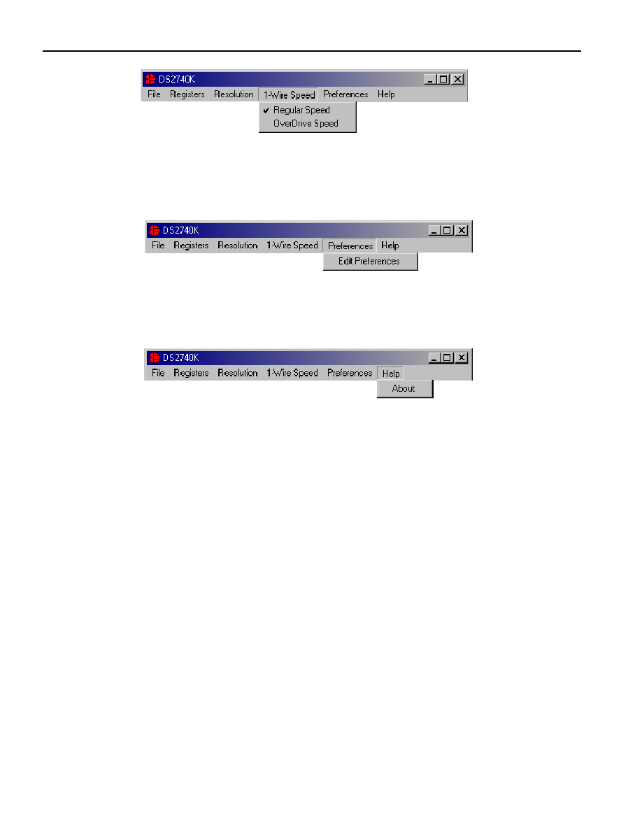
1-Wire Speed Menu
The 1-Wire
Æ
Speed Menu allows the user to select with which 1-wire speed the device is set. The speed is
determined by the state of the pin 1 (OVD pin). If pin 1 has a value of 1, the device communicates with 1-
wire overdrive timing. If pin 1 has a value of 0, the device communicates with regular 1-Wire timing.
Preferences Menu
The Preferences Menu allows the user to change COM port settings at any time. Edit Preferences opens
the Select Preferences window. See Selecting the COM Port above.
Help Menu
Selecting the About topic from the Help Menu will open a window containing information about this
program and Dallas Semiconductor.
PROGRAM TABS
All functions of the program are divided under four tabs in the main program window. Left click on the
appropriate tab to move to the desired function page. Located under the Meters tab is all information on
real-time updates measured by the DS2740: current, accumulated charge, and the state of the SMOD,
RNAOP and PIO bits of the Status and Special Feature Registers. The Data Log tab allows the user to
store all real-time information to a file. The Memory tab displays the contents of every register and
memory location inside the DS2740 and allows the user to alter the data. The Pack Information tab gives
the user the ability to choose with which device on the 1-Wire bus to communicate and set the value of
the sense resistor.
1-Wire is a registered trademark of Dallas Semiconductor.

DS2740K
5 of 9
Meters Tab
The Meters Screen displays the latest real-time measurements of current and accumulated charge with
both analog meter readouts and digital values. The sense resistor value used to calculate the current
reading is shown in the current section. Left click on it or go to the sense resistor sub-tab under Pack Info
to change this value.
The values of the SMOD, RNAOP, and PIO bits of the Status and Special Feature Registers are also
displayed. The user also has the ability to toggle the value of these bits by left clicking on the associated
button.
Set Accumulated Current Register
The user can bring up the Set Accumulated Current Register window by left clicking the Set ACR button.
This window allows the user to enter values for the Accumulated Current Register and Rated Battery
Capacity in mAH. Clicking the OK button will write the New ACR Value to the DS2740's Accumulated
Current Register. The Rated Battery Capacity is used to determine full-scale range on the Accumulated
Charge Meter and is only a software value; it is not stored on the device.