1 of 14
021201
FEATURES
Demonstrates the capabilities of the DS2760
Li
+
Battery Monitor, including:
-
Temperature measurement
-
Voltage measurement
-
Current measurement
-
Current accumulation
-
Information storage
-
Identification
-
Overvoltage/Undervoltage protection
-
Overcurrent/short circuit protection
Interfaces to the serial port of a PC running
Windows 95, Windows 98 or Windows NT
INDEX
Evaluation Kit Contents
Equipment Needed
Introduction
Setup and Installation
Board Connections
Software Installation
Selecting the COM Port
Program Menus
Register Windows
Program Tabs
Real Time Meters
Data Logging
User Memory
Pack Information
Fuel Gauging
EVALUATION KIT CONTENTS
2 pc. TSSOP or CSP Evaluation Boards
of different varieties
1 pc. DS9123 Serial Port Adapter
1 pc. RJ-11 Phone Cable
1 pc. DS2760K CD containing:
DS2760K Evaluation Software
DS2760 Related Data Sheets
EQUIPMENT NEEDED
1.
An IBM-compatible PC running Windows 95,
Windows 98 or Windows NT with a CD
ROM drive and an available serial port.
2.
Cables with mini-grabber style clips or the
ability to solder directly to connection pads.
3.
A Lithium-Ion battery and a power supply
and/or load circuit.
INTRODUCTION
The DS2760K Evaluation Kit makes performance evaluation, software development, and prototyping
with the DS2760 Lithium-Ion Battery Monitor easy. The evaluation board interfaces to an IBM-
compatible PC through a DS9123 Serial Port Adapter and RJ-11 cable connection. The provided CD
ROM contains all related data sheets along with the evaluation software, which can be run under
Windows 95, Windows 98 or Windows NT.
The DS2760K evaluation software gives the user complete control of all functions of the DS2760.
Separate control tabs allow the user access to all EEPROM and RAM memory locations, all control
registers, and real-time updates of all monitored parameters. The software also incorporates a data
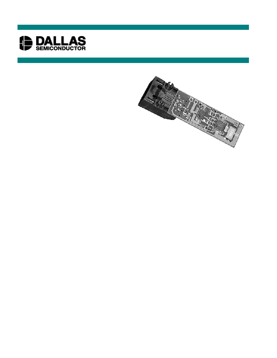
DS2760K
Li
+
Battery Monitor Evaluation Kit
www.dalsemi.com
PD070600
DS2760K TSSOP

DS2760K
2 of 14
logging feature to monitor a cell over time and fuel gauging algorithms to improve remaining capacity
calculations based on specific cell characteristics.
The evaluation board circuit is designed to provide the DS2760 with accurate parameter measurements,
allow the DS2760 to disable charging or discharging, and protect the DS2760 from ESD damage. Kit
demonstration boards will vary as they are improved upon over time. For information on the
demonstration board circuits refer to the DOCS browser page when auto running from the DS2760K CD
ROM or inside the documentation directory on the DS2760K CD ROM.
SETUP AND INSTALLATION
BOARD CONNECTIONS
Connections to the TSSOP demonstration board are best made either by soldering directly to the pads or
by using cables with mini-grabber clips. Connections to the CSP board are best made by soldering
directly to the pads. Communication to the TSSOP board can be accomplished either through the RJ-11
jack by connecting the provided standard six conductor phone cord or by wiring directly to the DQ and
PAC- pads. In the latter case, the size of the board can be reduced by snapping off the RJ-11 jack along
the break line, see figure 1. To utilize the demonstration software, the DQ and PAC- lines must be
connected to the DS9123 communication brick using either of the two methods described.
Figure 1: Communication Connections
Figures 2a and 2b show the recommended circuits to simulate charging and discharging. The Lithium-Ion
cell is connected between the BAT+ and BAT- pads. The battery charger/power supply or circuit load is
connected between the PAC+ and PAC- pads. The evaluation software can be run in either configuration
as long as a cell is connected between the BAT+ and BAT- terminals providing a minimum of 2.5 volts to
power the DS2760. Some board versions also have connections for the PS and PIO pins. Refer to the
datasheet for the operation of these pins. Leaving them unconnected does not interfere with the operation
of the demonstration board.
Figure 2a: Charging Circuit
Fig 2b: Discharging Circuit
DQ
RJ-11
Break Line
PAC
-
PAC
+
BA
T+
PIO
BA
T-
PS
BAT +
PAC -
PAC +
PS
BATTERY
+
-
D
S
276
0K
E
V
A
LU
A
T
ION
BOARD
DQ
Power
Supply /
Battery
Charger
LOAD
BAT-
PIO
BAT +
PAC -
PAC +
PS
BATTERY
+
-
D
S
276
0K
E
V
A
LU
A
T
ION
BOARD
DQ
BAT-
PIO
DS2760K
3 of 14
SOFTWARE INSTALLATION
To install the DS2760K software, exit all programs currently running and insert the DS2760K software
CD into your computer's CD ROM. The auto run software on the CD will give an option to install
DS2760K or the user can run SETUP.EXE from the setup directory and the installation process begins.
Follow the prompts to complete the installation. The DS2760K software can be uninstalled in the
Add/Remove Programs tool in the Control Panel. After the installation is complete, open the DS2760K
folder and run DS2760K.EXE or select DS2760K from the program menu. A splash screen containing
information about the evaluation kit appears as the program is being loaded.
The Documentation directory also located on the CD contains all relevant data sheets and application
notes on the DS2760 and DS2760K. They are stored in Adobe Acrobat format for easy viewing and can
also be accessed through the help menu after the program starts.
SELECTING THE COM PORT
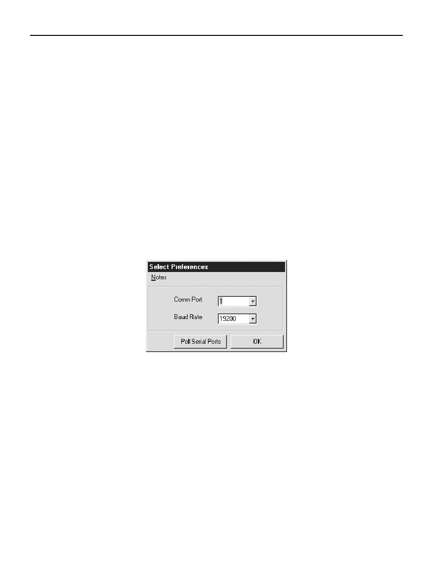
The first time the software runs, the Serial Port Settings window appears. In this window, select the
COM port to which the DS9123 is attached and the desired communication rate; then hit OK. The
DS2760K software saves this COM port selection and automatically uses the selection each time the
program starts. To change the COM port later, click the Preferences option on the menu bar, select Serial
Port Settings, and then select the appropriate port. To attempt to automatically locate the DS9123, click
the Poll Serial Ports button. Warning - automatically polling for the DS9123 can disrupt other devices
connected to your computer's COM ports.
MENUS
Several pull down menu options have been provided to simplify use of the DS2760K software for the
user. Their functions are individually detailed below.

DS2760K
4 of 14
FILE MENU
The File Menu allows the user to store information from a file directly into the Device Setup, Battery
Data, and Fuel Gauging Data sections under the Pack Info Tab or take the same Pack Information and
store to a file. These functions do not directly write or read the DS2760. It is still necessary for the user to
store or recall this information to or from the device by issuing a WRITE or READ command under the
Pack Info Tab.
DS2760K
5 of 14
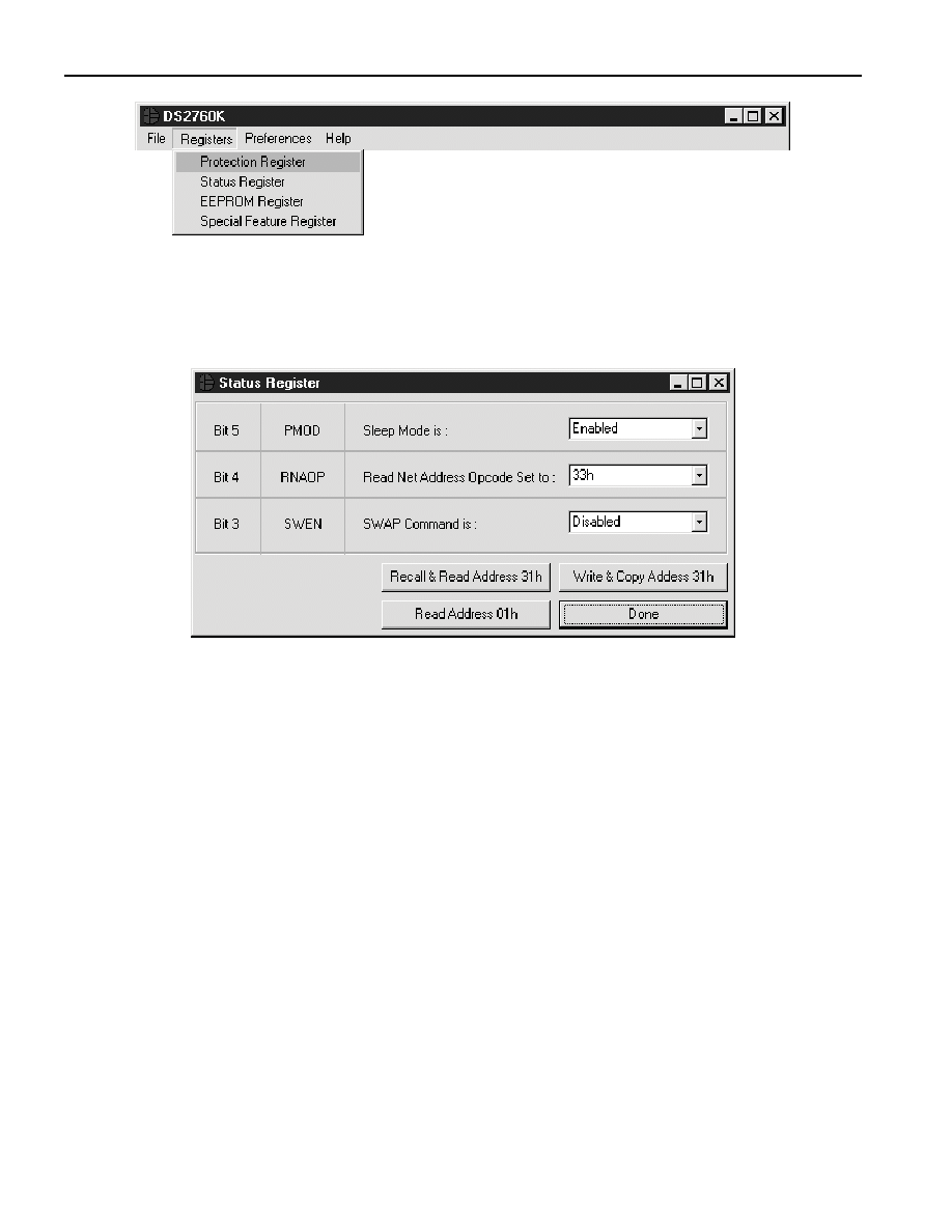
REGISTERS MENU
The Registers Menu gives immediate access to all four status and function registers of the DS2760.
Selecting any of the registers will open an individual control window giving the user a description of each
register bit and the ability to read or write it. See the protection register window example.
STATUS REGISTER
The present state of all register bits are displayed immediately upon opening the register window. R/W
locations contain a selection field to allow the user to determine their state. Pressing either the APPLY or
OK button in the EEPROM Register or Special Feature Register windows will automatically update and
read the corresponding register inside the DS2760. The Protection and Status registers have default values
stored in user EEPROM addresses 0x30h and 0x31h respectively. Their windows contain extra options to
write or read these locations independently of their registers.