1 of 11
REV: 110603
GENERAL DESCRIPTION
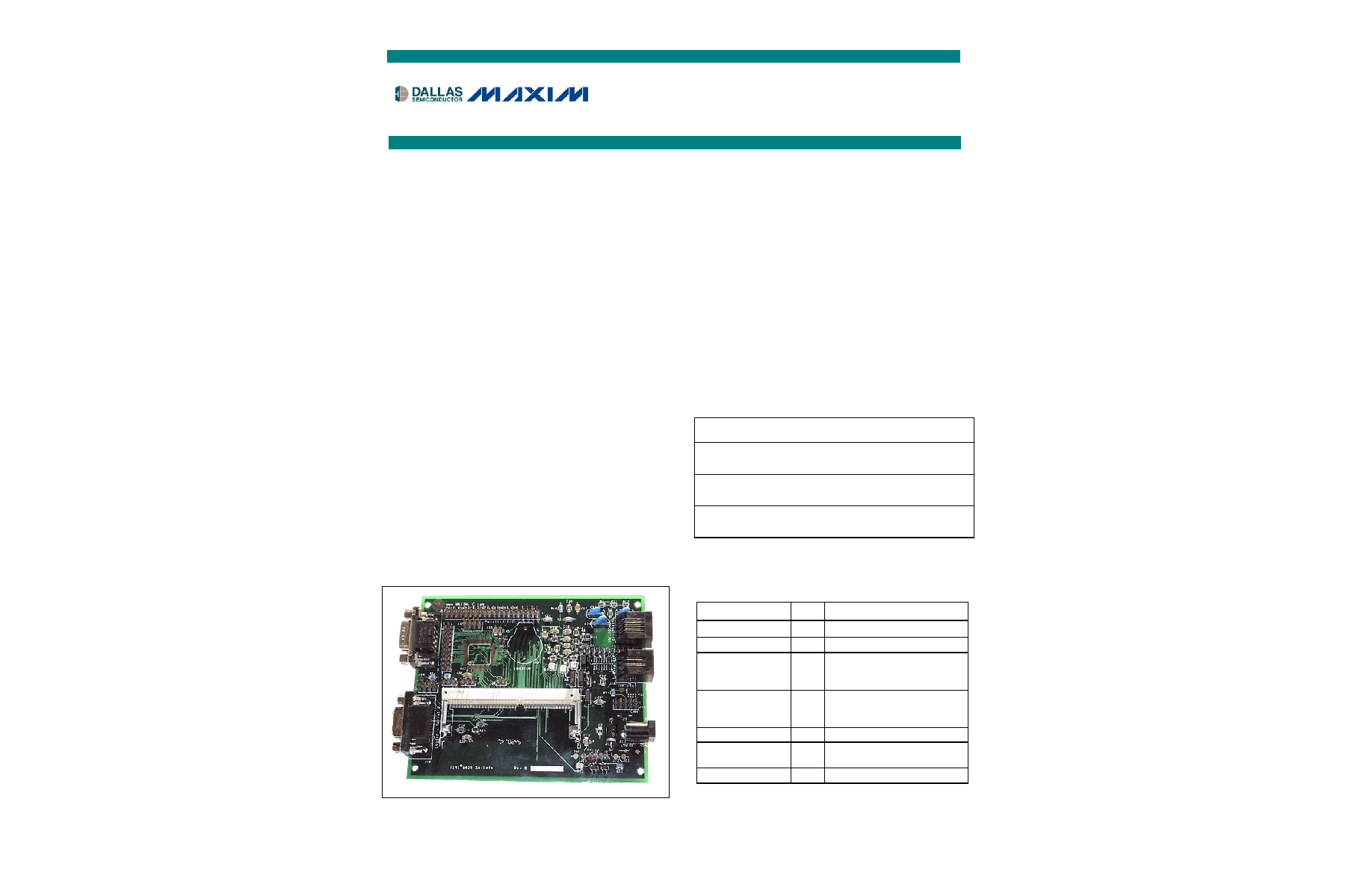
The TINI
Æ
sockets boards are motherboards
designed to host the corresponding TINI evaluation
module. The combination of the two boards allows
full evaluation of the features of the target
microprocessor. To evaluate the DS80C400, order
both a DSTINIm400 and a DSTINIs400.
Although various boards support different evaluation
modules, the most popular is the DSTINIs400. It
includes a 144-pin SODIMM connector and provides
1-Wire
Æ
, CAN2.0B, serial, and a 10/100 Ethernet
PHY for connecting the TINIm400 to the physical
world.
The DSTINIm400 and DSTINIs400 are fully
assembled and tested circuit boards. When used
together they form a complete evaluation system for
the DS80C400 network microcontroller. The
DSTINIm400 module includes the DS80C400
network microcontroller, a real-time clock, 1MB flash,
1MB static RAM, and support for an external
Ethernet PHY for connecting to a wide variety of
networks. The circuit board is designed as a module
to be plugged into the 144-pin SODIMM connector on
the DSTINIS400.
Detailed information about the initial setup process
and use of the TINI platform is contained in
Application Note 612: Getting Started with the
TINIm400 (DS80C400) Verification Module.
TINI and 1-Wire are registered trademarks of Dallas
Semiconductor.
FEATURES
ß
Hosts the TINI Runtime Environment in Validated
Hardware Design (in Conjunction with the
DSTINIm400)
ß
10/100 Base-T Ethernet Port
ß
Two Serial Ports
ß
Dual 1-Wire Network Ports
ß
CAN2.0B Port
ß
5.0V Single-Supply Operation (DSTINIm400)
ß
Fully Assembled and Tested Design
ORDERING INFORMATION
PART
INPUT
VOLTAGE*
USED WITH
MODULE
DIMENSIONS
DSTINIs400
5V DC
regulated
DSTINIm400
12cm x 10cm
DSTINIs-005
5V DC
regulated
DSTINI1-1MG,
DSTINI1-512
16cm x 10cm
DSTINIs-006
9V to 18V
DC
DSTINI1-1MG,
DSTINI1-512
16cm x 10cm
*The user must supply an external power supply.
COMPONENT LIST
DESIGNATION QTY
DESCRIPTION
C1 1
47pFcapacitor
(1206)
C2, C4≠C6
4
47
mF capacitors (1206)
C3, C7, C9, C13,
C15, C26, C28,
C30, C38
9 100nF
capacitors
(1206)
C12, C14, C17,
C19, C25, C27,
C29, C33, C37
9 10nF
capacitors
(1206)
C8 1
220nF
capacitor
(1206)
C10, C31, C32,
C34≠C36
6
1.0
mF capacitors (1206)
C11 1
4.7
mF capacitor (1206)
DSTINIs400/DSTINIs-00x
Sockets Evaluation Board
www.maxim-ic.com

DSTINIs400/DSTINIs-00x Sockets Evaluation Board
2 of 11
COMPONENT LIST (continued)
DESIGNATION QTY
DESCRIPTION
C16, C18
2
270pF capacitor (1206)
C20≠C22 3
1nF, 2kV thru-hole
capacitors
C23, C24
2
27pF capacitors (1206)
D1 1
1N5908
D0-201
D2 1
BAT54
SOT-23
J1 1
SODIMM144
Hirose SX6E-144S-0.8SH
J2 1
2.5mm center, 5.5mm
outside barrel connector
J7
1
RJ-45 modular jack
J9≠J11 3
3 x 1-pin headers, 0.1
centers
J12
1
DB9 serial female
J13 1
DB9
serial
male
J14 1
Pad
jumper
J16
1
RJ11 modular jack
L1 1
22
mH inductor
R1 1
205k
W, ±1% resistor (1206)
R2 1
121k
W, ±1% resistor (1206)
R4≠R7, R8,
R10≠R12
8
49.9
W, ±1% resistors (1206)
R13, R9
2
47
W resistor (1206)
R14 1
22.1k
W, ±1% resistor (1206)
R15, R17, R18
3
220
W resistors (1206)
R16 1
10k
W resistor (1206)
R19 1
Pad
jumper
DESIGNATION QTY
DESCRIPTION
R20 1
47k
W resistor (1206)
R21 1
124
W, ±1% resistor (1206)
R22, R23
2
1k
W resistor (1206)
R24 1
10k
W resistor (1206)
T1 1
BelFuse S558-5999-T7
transformer
U1 1
MAX1692 PWM step-down
regulator
U3 1
Intel LXT972ALC Ethernet
PHY
U4≠U6
3
Dialight 597-7741 LED
U7 1
MAX560CAI
transceiver
U8 1
DS2480B serial 1-Wire line
driver
U9 1
DS9502 ESD protection
diode
Y1 1
25.000MHz,
HC49
Z1≠Z3 3
Ferrite Bead, Fair-Rite
2512067007Y3
UNPOPULATED COMPONENTS
J15 1
DS9094F
iButton
Æ
Clip
J18, J28≠J30
1
Not used
U2 1
MAX1792EUA18 linear
regulator
U10 1
DS2408 1-Wire 8-channel
addressable switch
U12 1
Not
used
JUMPERS (DSTINIS400)
Network Boot Jumper (J3)
JUMPER CONFIGURATION
1≠2
DS80C400 attempts to boot through
Ethernet using DHCP and TFTP
Quiet Boot Jumper (J5)
JUMPER CONFIGURATION
1≠2
DS80C400 boots without sending loader
information to serial port.
Auto Negotiation Jumper (J9)
JUMPER CONFIGURATION
1≠2 Auto-negotiation
disabled.
2≠3 Auto-negotiation
enabled.
10/100Mb Ethernet Jumper (J10)
JUMPER CONFIGURATION
1≠2 100Mb
Ethernet
operation.
2≠3
10Mb Ethernet operation.
Full Duplex Jumper (J11)
JUMPER CONFIGURATION
1≠2
Ethernet is configured for full-duplex
operation.
2≠3
Ethernet is configured for half-duplex
operation.
DTR Reset Jumper (J11)
JUMPER CONFIGURATION
1≠2
DTR reset is used for communication with
the DS80C400 loader application.
iButton is a registered trademark of Dallas Semiconductor.

DSTINIs400/DSTINIs-00x Sockets Evaluation Board
3 of 11
PIN HEADERS
CONNNECTOR DESCRIPTION
J18
Recreated I/O Port. Latched from 1-Wire bus.
Requires installation of DS2408. See schematic.
J20
CAN Bus. See schematic for pinout.
J21
SPITM Bus. See schematic for pinout. Alternately
provides connection to P5.4≠P5.7
J27
I
2
CTM Bus. See schematic for pinout. Alternately
provides connection to P1.0 and P1.1.
J28
Unused. No user-accessible pins available.
J29
Unused. No user-accessible pins available.
J30
Unused. No user-accessible pins available.
QUICK START
Recommended Equipment
The sockets board requires an external power supply and cables as needed to access the desired features of the
board. The 5V DC power supply is mandatory, but the other cables are required only if that feature is to be used.
The specific example shown here is for a TINIm400/TINIs400 system.
Hardware:
5V DC Power Supply
Input Voltage: per customer requirements
Output Voltage: 5V DC ±10%
Output Current: >150mA
Polarization: Positive Center
Output Plug Type: 2.5mm I.D. x 5.5mm O.D. x 12mm Female (P-6)
Example: Digi-Key (www.digikey.com) part number T309-P6P-ND (110V input), 5V DC power
Ethernet Cable:
Note: There are two types of Ethernet cable. For connection to a router or hub, use a standard "straight-through"
Ethernet cable. For direct connection to an Ethernet port on the back of a PC, use a "crossover" Ethernet cable. A
crossover cable is specially made for two-computer networking. These cables can be purchased from almost any
computer or electronics store.
Example (straight-through): Radio Shack (www.radioshack.com) Cat 5E (3ft) Network Cable, part number 278-
1763
Example (crossover): Radio Shack Cat 5E (3m) Crossover Cable, part number 278-2011
RS-232C Serial Cable (DB9 Male to DB9 Female):
This cable is straight-through, not a null-modem (crossover). These cables can be purchased from any computer or
electronics store.
SPI is a trademark of Motorola, Inc.
I
2
C is a trademark of Philips Corp. Purchase of I
2
C components of Maxim Integrated Products, Inc., or one of its sublicensed Associated
Companies, conveys a license under the Philips I
2
C Patent Rights to use these components in an I
2
C system, provided that the system
conforms to the I
2
C Standard Specification as defined by Philips.

DSTINIm400/DSTINIs-00x Sockets Evaluation Board
4 of 11
MORE INFORMATION
TINI platform details can be found at
www.maxim-ic.com/TINI
. The TINI Specification and Developer's Guide
(Addison-Welsey, 2001) is an invaluable resource when developing with the TINI platform. Download a free copy
from our website at
www.maxim-ic.com/TINIguide
.
Additional Resources
For detailed information about the initial setup and use of the TINI platform, refer to Application Note 612: Getting
Started with the TINIm400 (DS80C400) Verification Module at
www.maxim-ic.com/appnoteindex
.
DS80C400 network microcontroller data sheet:
www.maxim-ic.com/DS80C400
Microcontroller Website:
www.maxim-ic.com/microcontrollers

P50
T x C l k
M D I O
VCC3
T x D 3
P52
P53
R x D 2
R x D 0
n R s t O u t
P30
C O L
TxEn
P16
P12
P14
R x E r
P51
M D C
T x D 1
n R s t I n
P67
C R S
P17
P11
P13
P15
R x C l k
R x D V
R x D 1
T x D 2
P66
R x D 3
T x D 0
P10
P33
P31
P32
n C E 0
n C E 1
n C E 2
D 0
D 1
D 2
D 3
D 4
D 5
D 7
D 6
n P C E 1
n P C E 3
n P C E 0
n P C E 2
n C E 7
n C E 6
n C E 5
n C E 4
n C E 3
V50
V33
P
6[7:6]
nR
stIn
nRstO
ut
TxEn
TxD
[3:0]
TxClk
RxDV
RxC
lk
RxEr
RxD
[3:0]
C
OL
C
RS
MDC
MD
IO
P
1[7:0]
P
3[3:0]
P
5[3:0]
D
[7:0]
Lo
cal1W
nWr
n
Rd
ALE
nPS
En
A16
A17
A18
A19
A20
A21
n
PCE[3:0]
nCE
[7:3]
A2
A1
A3
A0
T
itle
S
ize
Do
cument Number
Rev
Date:
TI
NIs400
B
TINIm400 Socket Board: TINI Module
Connector
B
1
7
Monday, March 04, 2
002
J1
DI
MM144
G N D 1
1
G N D 2
2
V C C 3
3
V C C 4
4
A13
5
nRstIn
6
A16
7
n R a m 2 E n
8
A15
9
A 8
10
A14
11
A 9
12
A17
13
A11
14
A20
15
n P S E N
16
A19
17
A10
18
D 6
19
D 7
20
D 5
21
D 3
22
D 4
23
nFlashEn
24
D 2
25
A 0
26
D 1
27
A 4
28
D 0
29
P1.4
30
A 3
31
P1.5
32
A 2
33
n R a m 1 E n
34
A 1
35
P1.3
36
A12
37
P1.2
38
P1.6
39
P1.1
40
P1.7
41
P1.0
42
nRstOut
43
n E A
44
C R S
45
TxEn
46
C O L
47
RxEr
48
R x D V
49
M D C
50
MDIO
51
G N D 5 2
52
G N D 5 3
53
TxD.3
54
TxD.2
55
TxD.1
56
TxD.0
57
G N D 5 8
58
G N D 5 9
59
TxClk
60
RxClk
61
G N D 6 2
62
G N D 6 3
63
RxD.0
64
RxD.1
65
RxD.2
66
RxD.3
67
G N D 6 8
68
G N D 6 9
69
N C 7 0
70
P3.0
71
A L E
72
P3.1
73
P5.3
74
P3.2
75
n P C E 1
76
N C 7 7
77
n P C E 3
78
P3.3
79
n P C E 0
80
N C 8 1
81
n P C E 2
82
n W r
83
N C 8 4
84
nRd
85
N C 8 6
86
P5.2
87
N C 8 8
88
N C 8 9
89
N C 9 0
90
N C 9 1
91
N C 9 2
92
N C 9 3
93
N C 9 4
94
P5.1
95
P5.0
96
A18
97
n C E 3
98
n C E 2
99
n C E 1
100
n C E 0
101
P6.7
102
P6.6
103
A21
104
n C E 7
105
n C E 6
106
n C E 5
107
n C E 4
108
A 5
109
N C 1 0 9
110
A 6
111
N C 1 1 2
112
A 7
113
N C 1 1 4
114
N C 1 1 5
115
Local1W
116
N C 1 1 7
117
vPullup
118
N C 1 1 9
119
N C 1 2 0
120
N C 1 2 1
121
N C 1 2 2
122
N C 1 2 3
123
N C 1 2 4
124
N C 1 2 5
125
N C 1 2 6
126
N C 1 2 7
127
N C 1 2 8
128
N C 1 2 9
129
N C 1 3 0
130
N C 1 3 1
131
N C 1 3 2
132
N C 1 3 3
133
N C 1 3 4
134
N C 1 3 5
135
N C 1 3 6
136
N C 1 3 7
137
N C 1 3 8
138
N C 1 3 9
139
N C 1 4 0
140
V C C 1 4 1
141
V C C 1 4 2
142
G N D 1 4 3
143
G N D 1 4 4
144
Copyright (C) 2003 Dallas Semiconductor / Maxim
n E x t I n t
V C C 5
V C C 3
V C C 3
V C C 3
V 3 3
V 1 8
V 5 0
V 3 3
P 5 3
P 1 7
P 5 2
P 3 2
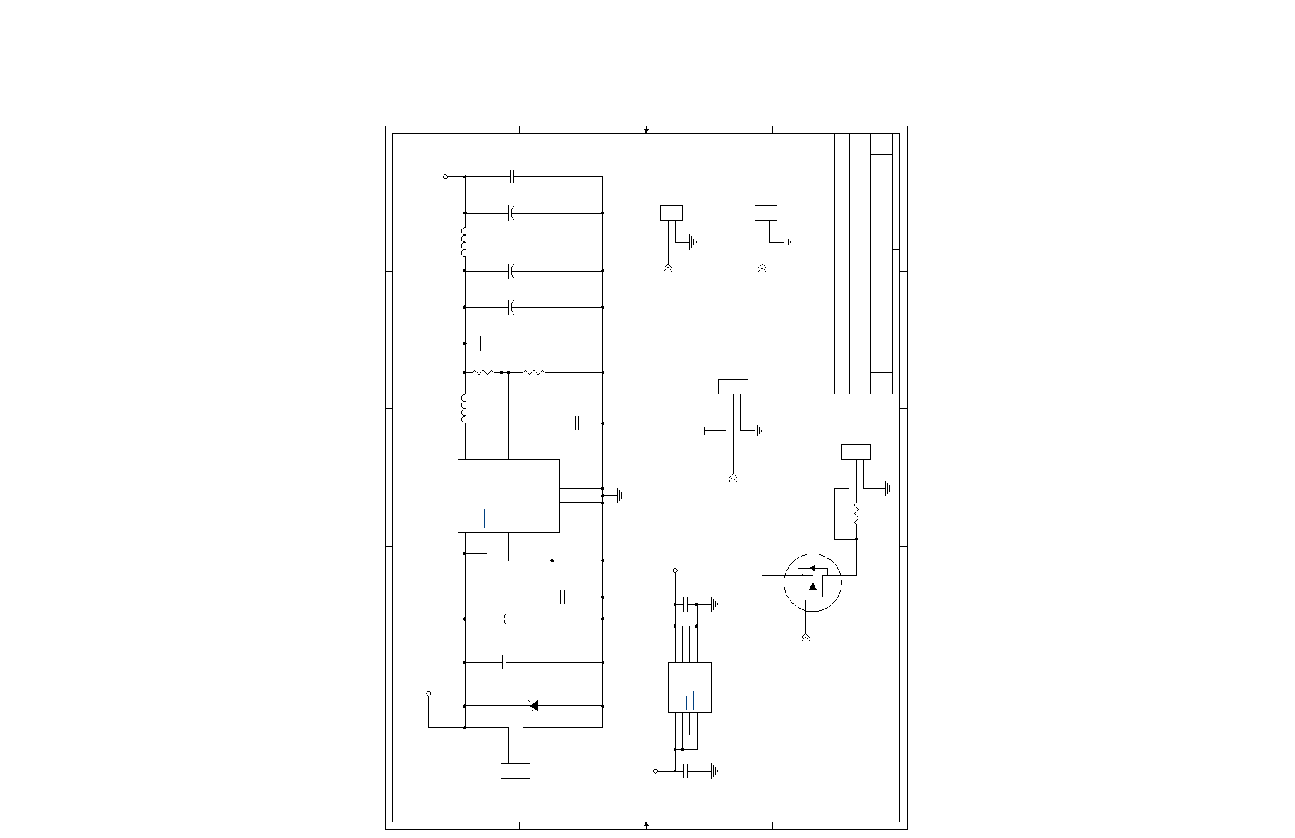
Title
Size
D o c u m e n t N u m b e r
R e v
D a t e :
T I N I s 4 0 0
B
T I N I m 4 0 0 S o c k e t B o a r d : P o w e r a n d I n t e r n a l s
A
2
7
M o n d a y , M a r c h 0 4 , 2 0 0 2
!
"
J 3
2Pin
1
2
+
C 4
4 7 u F
J 6
3Pin
1
2
3
D1
1N5908
C 7
0 . 1 u F
Q 1
B S S 8 4
C 8
0 . 2 2 u F
+
C 6
4 7 u F
R 3
1 0 K
L 1
2 2 u H
Z 1
B e a d
R 1
2 0 5 K 1 %
U 1
MAX1692
IN
1
L I M
6
S H D N
8
R E F
4
B P
2
L X
9
F B
5
S Y N C / P W M
7
GND
3
PGND
10
R 2
1 2 1 K 1 %
C 9
0 . 1 u F
C 1
4 7 p F
J 4
3Pin
1
2
3
C 3
0 . 1 u F
+
C 2
4 7 u F
+
C 5
4 7 u F
C 1 1
4 . 7 u F
J 5
2Pin
1
2
J 2
87-72010-004
1
2
3
U 2
M A X 1 7 9 2 E U A 1 8
IN2
2
R S T
3
S H D N
4
O U T 1
8
O U T 2
7
S E T
6
G N D
5
IN1
1
C 1 0
1 . 0 u F
Copyright (C) 2003 Dallas Semiconductor / Maxim
T x D 2
T x D 1
R x D 1
R x D 2
R x D 3
T x D 0
T x D 3
R x D 0
V C C 3
V C C 3
V C C 3
V C C 3
V C C 3
V C C 3
R x E r
n R s t O u t
T x D [ 3 :0]
C O L
M D C
C R S
R x C l k
T x E n
M D I O
R x D V
R x D [ 3 : 0 ]
T x C l k
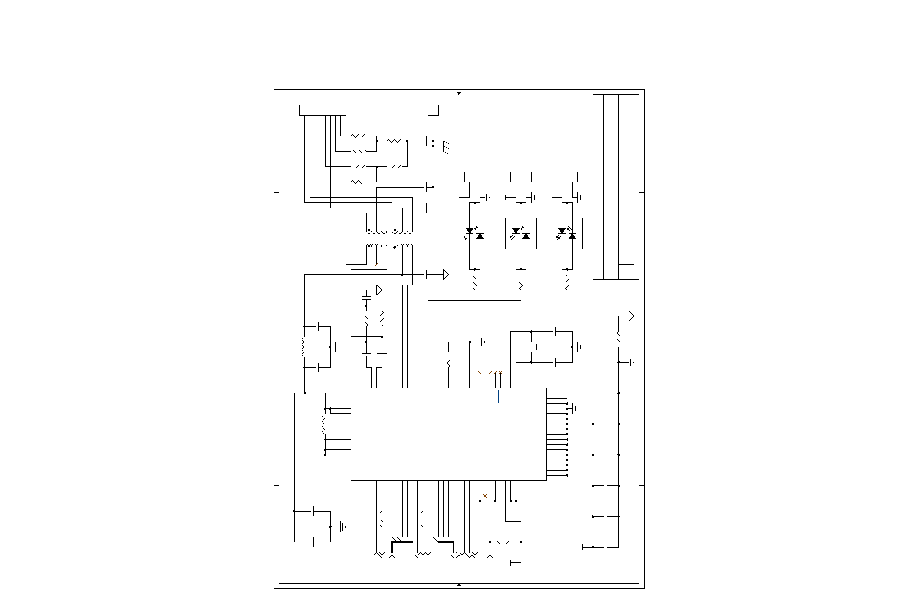
Title
Size
D o c u m e n t N u m b e r
R e v
D a t e :
T I N I s 4 0 0
B
T I N I m 4 0 0 S o c k e t B o a r d : E t h e r n e t
A
3
7
M o n d a y , M a r c h 0 4 , 2 0 0 2
#$ ##%
%
&
&'
&'
&'
1%
1%
1%
1%
C 1 4
0 . 0 1 u F
C 1 5
0 . 1 u F
C 2 0
0 . 0 0 1 u F , 2 k V
R 1 7
2 2 0
C 1 6
2 7 0 p F
C 2 1
0 . 0 0 1 u F , 2 k V
C 1 8
2 7 0 p F
R 1 6
1 0 K
C 1 9
0 . 0 1 u F
U 5
5 9 7 - 7 7 4 1
1
2
3
4
C 2 2
0 . 0 0 1 u F , 2 k V
Y 1
2 5 . 0 0 0 M H z
U 3
LXT972A L C
XI
1
X O
2
M D D I S
3
R E S E T
4
S L E W 0
5
S L E W 1
6
GND1
7
VCCIO1
8
GND2
11
A D D R 0
1 2
GND3
13
GND4
14
GND5
15
GND6
16
R B I A S
1 7
GND7
18
T P O P
1 9
T P O N
2 0
VCCA1
21
VCCA2
22
T P I P
2 3
T P I N
2 4
GND9
25
GND10
26
T D I
2 7
T D O
2 8
T M S
2 9
T C K
3 0
T R S T
3 1
GND8
32
M D I N T
6 4
C R S
6 3
C O L
6 2
GND13
61
T X D 3
6 0
T X D 2
5 9
T X D 1
5 8
T X D 0
5 7
T X _ E N
5 6
T X _ C L K
5 5
T X _ E R
5 4
R X _ E R
5 3
R X _ C L K
5 2
VCCD
51
GND12
50
R X _ D V
4 9
R X D 0
4 8
R X D 1
4 7
R X D 2
4 6
R X D 3
4 5
M D C
4 3
M D I O
4 2
GND11
41
VCCIO2
40
P W R D W N
3 9
L E D _ C F G 1
3 8
L E D _ C F G 2
3 7
L E D _ C F G 3
3 6
TEST1
35
TEST0
34
P A U S E
3 3
C 2 3
2 7 p F
R 1 3 4 7
C 2 4
2 7 p F
R 1 5
2 2 0
R 8
4 9 . 9 1 %
R 1 0
4 9 . 9 1 %
J 1 0
3 P i n
1
2
3
C 2 5
0 . 0 1 u F
R 1 4
2 2 . 1 K 1 %
R 1 9
0 O h m
U 6
5 9 7 - 7 7 4 1
1
2
3
4
C 2 6
0 . 1 u F
R 1 8
2 2 0
R 7
4 9 . 9
C 2 7
0 . 0 1 u F
R 6
4 9 .9
R 5
4 9 .9
J 9
3 P i n
1
2
3
C 3 0
0 . 1 u F
R 4
4 9 .9
J 7
R J - 4 5
1
2
3
4
5
6
7
8
C 1 7
0 . 0 1 u F
R 1 1
4 9 . 9 1 %
C 2 9
0 . 0 1 u F
R 1 2
4 9 . 9 1 %
C 2 8
0 . 1 u F
Z 2
B E A D
Z 3
B E A D
C 1 2
0 . 0 1 u F
C 1 3
0 . 1 u F
J 8
P a d
1
R 9
4 7
J 1 1
3 P i n
1
2
3
U 4
5 9 7 - 7 7 4 1
1
2
3
4
T1
S 5 5 8 _ 5 9 9 9 _ T 7
1
8
6
3
1 6
1 4
1 1
9
2
7
1 0
1 5
Copyright (C) 2003 Dallas Semiconductor / Maxim

TX0
D T R 4
R T S 4
TX4
RX0
D T R 0
RX4
C T S 4
D C D 4
D C D 4 _ 2 3 2
C T S 4 _ 2 3 2
R X 4 _ 2 3 2
TX4_232
D T R 4 _ 2 3 2
R T S 4 _ 2 3 2
TX0_232
R X 0 _ 2 3 2
D T R 0 _ 2 3 2
V C C 3
P 3 1
P 1 5
P 1 6
P 6 7
P 3 0
P 6 6
P 3 3
P 1 4
n R s t I n
n S h D n
Title
Size
D o c u m e n t N u m b e r
R e v
D a t e :
T I N I s 4 0 0
B
T I N I m 4 0 0 S o c k e t B o a r d : I n t e r n a l S e r i a l Ports 0 and 4
A
4
7
M o n d a y , M a r c h 0 4 , 2 0 0 2
#
J 1 2
D B 9 F E M A L E ( D C E )
1
2
3
4
5
6
7
8
9
J 1 3
D B 9 M A L E ( D T E)
1
2
3
4
5
6
7
8
9
+
C 3 1
1 u F
C 3 3
0 . 0 1 u F
R 2 0
4 7 K
+
C 3 4
1 u F
U 7
M A X 5 6 0 C A I
C1+
12
C1-
14
T 1 I N
7
T 2 I N
6
T 3 I N
2 0
T 4 I N
2 1
R 1 O U T
8
R 2 O U T
5
R 3 O U T
2 6
R 4 O U T
2 2
R 5 O U T
1 9
V+
13
VCC
11
EN
24
SHDN
25
C2+
15
C2-
16
GND
10
V-
17
T 1 O U T
2
T 2 O U T
3
T 3 O U T
1
T 4 O U T
2 8
R 1 I N
9
R 2 I N
4
R 3 I N
2 7
R 4 I N
2 3
R 5 I N
1 8
J 1 4
P A D J U M P E R
+
C 3 2
1 u F
+
C 3 5
1 u F
+
C 3 6
1 u F
Copyright (C) 2003 Dallas Semiconductor / Maxim
TX1
X O W I O
RX1
V C C 5
V C C 5
V C C 5
P 1 3
P 1 2
L o c a l 1 W
n E x t I n t
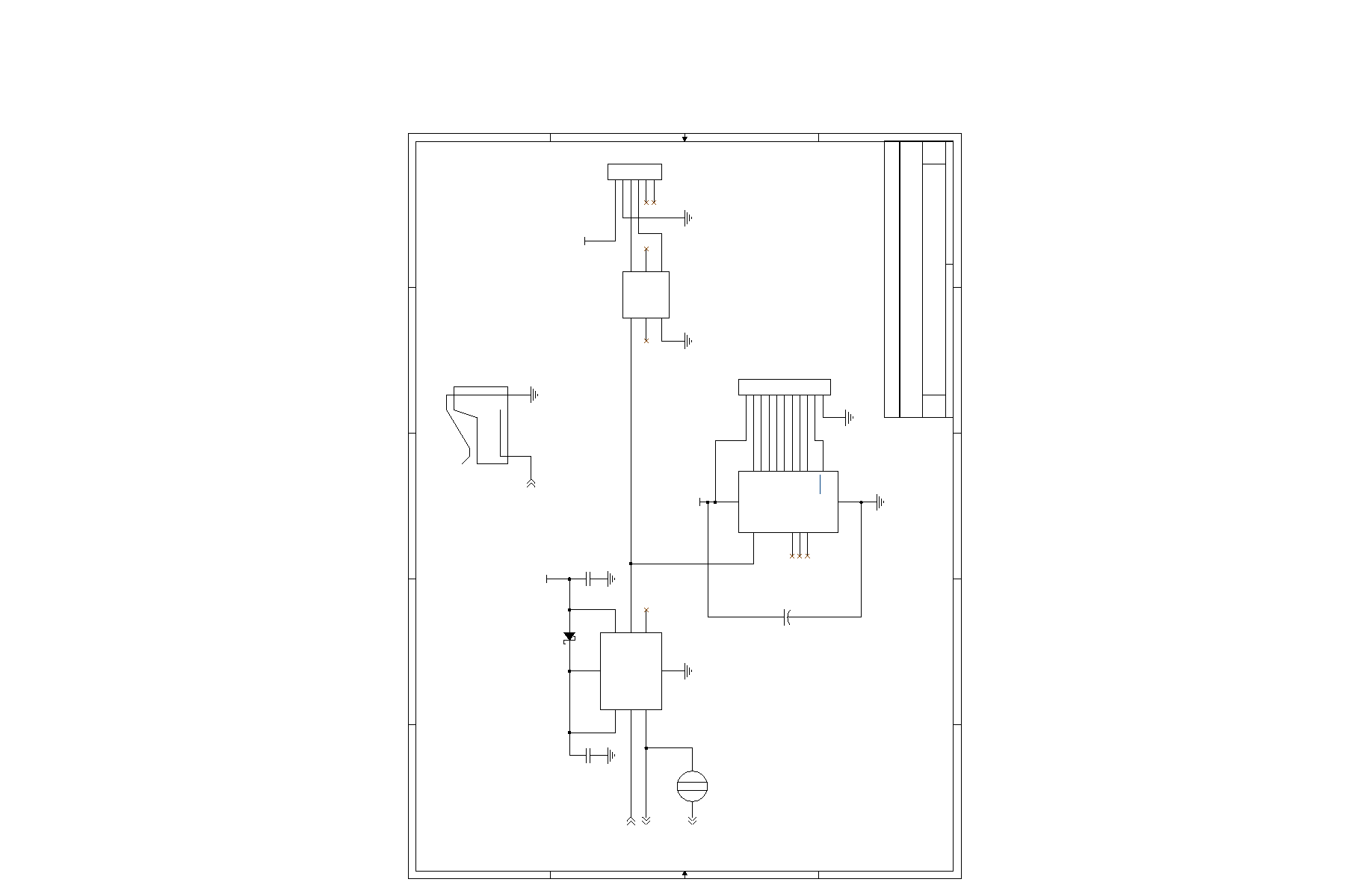
Title
Size
D o c u m e n t N u m b e r
R e v
D a t e :
T I N I s 4 0 0
B
T I N I m 4 0 0 S o c k e t B o a r d : E x t e r n a l 1 - W i r e I n t e r f a c e a n d D S 2 4 0 8
A
5
7
M o n d a y , M a r c h 0 4 , 2 0 0 2
%
"
%
( $
&
U 9
D S 9 5 0 2
C 1
1
A 1
2
N C 1
3
C 2
6
N C 2
4
A 2
5
J 1 7
P a d J u m p e r
C 3 7
0 . 0 1 u F
J 1 8
1 1 x 1
1
2
3
4
5
6
7
8
9
1 0
1 1
C 3 8
0 . 1 u F
J 1 5
D S 9 0 9 4 F
U 8
D S 2 4 8 0 B
GND
1
VDD
4
T X D
7
R X D
8
P O L
6
N C
3
O W I O
2
V P P
5
D 2
B A T 5 4
U 1 0
D S 2 4 0 8
N C 1
1
N C 1 5
1 5
N C 1 6
1 6
VCC
3
O W I O
4
GND
5
S T R B
1 0
P 0
2
P 1
1 4
P 2
1 3
P 3
1 2
P 4
1 1
P 5
9
P 6
8
P 7
7
+
C 3 9
4 7 u F
J 1 6
R J 1 1
1
2
3
4
5
6
Copyright (C) 2003 Dallas Semiconductor / Maxim

C0TX
C 0 R X
S D A
S C L K
n P C E 0
n P C E 1
n P C E 2
n P C E 3
V C C 3
V C C 5
V C C 5
V C C 5
V C C 3
V C C 5
V C C 3
V C C 5
V C C 5
V 5 0
V 3 3
V 3 3
P 5 0
P 5 1
P 1 0
P 1 1
n P C E [ 3 : 0 ]
n S h D n
Title
Size
D o c u m e n t N u m b e r
R e v
D a t e :
T I N I s 4 0 0
B
T I N I m 4 0 0 S o c k e t B o a r d : O t h e r I / O
A
6
7
M o n d a y , M a r c h 0 4 , 2 0 0 2
D 4
B A T 5 4 S
1
2
3
R 2 2
1 K
J 1 9
R 2 1
1 2 4
J 2 1
4 x 2
1
2
3
4
5
6
7
8
R 2 3
1 K
C 4 0
0 . 1 u F
J 2 6
P a d J u m p e r
J 2 0
5 x 2
1
2
3
4
5
6
7
8
9
1 0
J 2 7
4 H E A D E R P I N S , 0 . 1 "
1
2
3
4
R 2 4
1 0 K
J 2 2
J 2 3
J 2 4
U 1 1
S N 6 5 H V D 2 3 0
VCC
3
GND
2
R S
8
C A N H
7
C A N L
6
T X D
1
R X D
4
V R E F
5
J 2 5
D 3
B A T 5 4 S
1
2
3
Copyright (C) 2003 Dallas Semiconductor / Maxim

D 7
D 6
D 5
D 4
D 3
D 2
D 1
D 0
n C E 3
n C E 4
n C E 5
n C E 6
n C E 7
A1
A2
A3
A0
A21
A17
A19
A20
A18
A16
U I O 0
U I O 1
U I O 2
U I O 3
U I O 4
U
IO5
U I O 7
U I O 8
U I O 9
U I O 1 0
U I O 1 1
U I O 1 2
U I O 1 3
U I O 1 4
U I O 1 5
U I O 1 6
U I O 1 7
U I O 1 8
U I O 1 9
U I O 2 0
U I O 2 1
U I O 6
UI
O32
UI
O31
UI
O30
UI
O29
UI
O28
UI
O27
UI
O26
UI
O25
UI
O23
UI
O24
UI
O22
XIO0
XIO1
XIO2
XIO3
XIO5
XIO6
XIO7
XIO15
XIO14
XIO13
XIO12
XIO11
XIO10
XIO9
XIO8
XIO0
XIO1
XIO2
XIO3
XIO4
XIO5
XIO6
XIO7
XIO8
XIO9
X I O 1 0
X I O 1 1
X I O 1 2
X I O 1 3
X I O 1 4
X I O 1 5
U I O 0
U I O 1
U I O 2
U I O 3
U I O 4
U I O 5
U I O 6
U I O 7
U I O 8
U I O 9
U I O 1 0
U I O 1 1
U I O 1 2
U I O 1 3
U I O 1 4
U I O 1 5
U I O 1 6
U I O 1 7
U I O 1 8
U I O 1 9
U I O 2 0
U I O 2 1
U I O 2 2
U I O 2 3
U I O 2 4
U I O 2 5
U I O 2 6
U I O 2 7
U I O 2 8
U I O 2 9
U I O 3 0
U I O 3 1
U I O 3 2
XIO4
TDO
T D O
V 1 8
V 1 8
V 3 3
V 3 3
V 3 3
V 1 8
V 3 3
D [ 7 : 0 ]
A L E
n R s t O u t
n P S E n
n R d
n W r
n C E [ 7 :3]
A [ 3 :0]
A [ 2 1 : 1 6]
n E x t I n t
P 5 3
P 1 7
Title
Size
D o c u m e n t N u m b e r
R e v
D a t e :
D S T I N I s 4 0 0
B
P r o g r a m m a b l e I/O
A
7
7
M o n d a y , M a r c h 0 4 , 2 0 0 2
each U12 V33 connection
One 10 nF ceramic capacitor for
each U12 V18 connection
One 10 nF ceramic capacitor for
One 100 nF ceramic capacitor
for each U12 V33 connection
One 100 nF ceramic capacitor
for each U12 V18 connection
J 2 9
2 0 P i n d u al
1
2
3
4
5
6
7
8
9
1 0
1 1
1 2
1 3
1 4
1 5
1 6
1 7
1 8
1 9
2 0
C 4 2
1 0 0 n F
C 4 1
1 0 0 n F
C 5 1
1 0 n F
C 4 7
1 0 0 n F
C 5 7
1 0 n F
C 4 9
1 0 n F
C 4 3
1 0 0 n F
C 5 0
1 0 n F
J 3 0
8Pin
1
2
3
4
5
6
7
8
C 4 8
1 0 0 n F
J 2 8
4 0 P i n d ual
1
2
3
4
5
6
7
8
9
1 0
1 1
1 2
1 3
1 4
1 5
1 6
1 7
1 8
1 9
2 0
2 1
2 2
2 3
2 4
2 5
2 6
2 7
2 8
2 9
3 0
3 1
3 2
3 3
3 4
3 5
3 6
3 7
3 8
3 9
4 0
C 5 4
1 0 n F
C 5 5
1 0 n F
U 1 2
X C 2 C 6 4 - 7 V Q 1 0 0 C
I O 1
1
I O 2
2
I O 3
3
I O 4
4
V A U X
5
I O 6
6
I O 7
7
I O 8
8
I O 9
9
I O 1 0
1 0
I O 1 1
1 1
I O 1 2
1 2
I O 1 3
1 3
I O 1 4
1 4
I O 1 5
1 5
I O 1 6
1 6
I O 1 7
1 7
I O 1 8
1 8
I O 1 9
1 9
V x x
2 0
G N D 2 1
2 1
I O 2 2
2 2
I O 2 3
2 3
I O 2 4
2 4
G N D
2 5
V18a
26
IO27
27
IO28
28
IO29
29
IO30
30
GND1
31
IO32
32
IO33
33
IO34
34
IO35
35
IO36
36
IO37
37
VIO1
38
IO39
39
IO40
40
IO41
41
IO42
42
IO43
43
IO44
44
TDI
45
IO46
46
TMS
47
TCK
48
IO49
49
IO50
50
G N D 4
7 5
I O 7 4
7 4
I O 7 3
7 3
I O 7 2
7 2
I O 7 1
7 1
I O 7 0
7 0
G N D 3
6 9
I O 6 8
6 8
I O 6 7
6 7
I O 6 6
6 6
I O 6 5
6 5
I O 6 4
6 4
I O 6 3
6 3
G N D 2
6 2
I O 6 1
6 1
I O 6 0
6 0
I O 5 9
5 9
I O 5 8
5 8
V 1 8 b
5 7
I O 5 6
5 6
I O 5 5
5 5
I O 5 4
5 4
I O 5 3
5 3
I O 5 2
5 2
V I O 2
5 1
GND6
100
IO99
99
VIO4
98
IO97
97
IO96
96
IO95
95
IO94
94
IO93
93
IO92
92
IO91
91
IO90
90
IO89
89
VIO3
88
IO87
87
IO86
86
IO85
85
GND5
84
TDO
83
IO82
82
IO81
81
IO80
80
IO79
79
IO78
78
IO77
77
IO76
76
C 4 5
1 0 0 n F
C 5 6
1 0 n F
C 5 3
1 0 n F
C 5 2
1 0 n F
C 4 6
1 0 0 n F
C 4 4
1 0 0 n F
Copyright (C) 2003 Dallas Semiconductor / Maxim