 | –≠–ª–µ–∫—Ç—Ä–æ–Ω–Ω—ã–π –∫–æ–º–ø–æ–Ω–µ–Ω—Ç: MAX1068 | –°–∫–∞—á–∞—Ç—å:  PDF PDF  ZIP ZIP |

General Description
The MAX1168 evaluation system (EV system) is a com-
plete 8-channel, 16-bit data-acquisition system that is
comprised of a MAX1168 evaluation kit (EV kit) and a
Maxim 68HC16MODULE-DIP microcontroller (µC)
module.
Order the complete EV system (MAX1168EVC16) for a
comprehensive evaluation of the MAX1168 using a per-
sonal computer (PC). Order the EV kit (MAX1168EVKIT)
separately if the 68HC16MODULE-DIP module has
been purchased with a previous Maxim EV system, or
for custom use in other µC-based systems.
Features
o Proven PC Board Layout
o Windows
Æ
95/98/2000/XP-Compatible Evaluation
Software
o Convenient On-Board Test Points
o Fully Assembled and Tested
Evaluates: MAX1068/MAX1168
MAX1168 Evaluation Kit/Evaluation System
________________________________________________________________ Maxim Integrated Products
1
19-2994; Rev 0; 9/03
MAX1168EVC16 System
Component List
For pricing, delivery, and ordering information, please contact Maxim/Dallas Direct! at
1-888-629-4642, or visit Maxim's website at www.maxim-ic.com.
Ordering Information
MAX1168EVKIT Component List
Windows is a registered trademark of Microsoft Corp.
PART
IC PACKAGE
INTERFACE TYPE
MAX1168EVKIT
24 QSOP
User-supplied
MAX1168EVC16
24 QSOP
Windows software
Component Suppliers
SUPPLIER
PHONE
WEBSITE
Fairchild
Semiconductor
888-522-5372
www.fairchildsemi.com
TDK
847-803-6100
www.component.tdk.com
DESIGNATION
QTY
DESCRIPTION
C1≠C18, C21,
C22
20
0.1µF ± 10%, 16V X7R ceramic
capacitors (0603)
TDK C1608X7R1C104KT
C19, C20
2
10µF ± 20%, 16V X5R ceramic
capacitors (1210)
TDK C3225X5R1C106M
C23
1
1µF ± 20%, 10V X5R ceramic
capacitor (0805)
TDK C2012X5R1A105M
C24≠C31
8
100pF ceramic capacitors (0603)
TDK C1608C0G1H101J
C32≠C39
8
0.22µF ± 10%, 10V X7R ceramic
capacitors (0603)
TDK C1608X7R1A224K
FB1, FB2
2
Surface-mount ferrite beads (0603)
TDK MMZ1608B601C
R1≠R8
8
100
± 5% resistors (0603)
DESIGNATION
QTY
DESCRIPTION
R9≠R16
8
4.7k
± 5% resistors (0603)
R17≠R24
8
10
± 5% resistors (0603)
U1
1
16-bit ADC (24-pin QSOP)
Maxim MAX1168CCEG
U2
1
Logic buffer (5-SOT23)
Fairchild Semiconductor NC7SZ125
U3≠U10
8
Op amps (SOT23-5)
Maxim MAX4430EUK
J1
1
2 x 20 right-angle female connector
Samtec SSW-120-02-S-D-RA
TB0
1
2-circuit terminal block
JU1
1
2-pin header
JU2
1
3-pin header
None
2
Shunts
None
1
PC board, MAX1168 EV kit
None
1
MAX1168 EV kit software, CD-ROM
PART
QTY
DESCRIPTION
MAX1168EVKIT
1
MAX1168 EV Kit
68HC16MODULE-DIP
1
68HC16 µC Module
Note: Please indicate you are using the MAX1168 when con-
tacting these component suppliers.
Note: The MAX1168 software is included with the MAX1168 EV
kit but is designed for use with the complete EV system. The EV
system includes a µC module and the EV kit. If the Windows
software is not required, the EV kit board can be purchased by
itself, without the µC module.
Note: To evaluate the MAX1068, request a free sample of the
MAX1068_CEG when ordering the MAX1168 EV kit.

Evaluates: MAX1068/MAX1168
MAX1168 Evaluation Kit/Evaluation System
2
_______________________________________________________________________________________
Quick Start
Recommended Equipment
∑ MAX1168EVC16 (MAX1168EVKIT board and
68HC16MODULE-DIP)
∑ Three DC power supplies:
+8V to +20V at 0.25A
+5V at 0.2A
-5V at 0.2A
∑ Analog signal source:
0 to 4.096V
∑ Windows 95/98/2000/XP-compatible computer with
an available serial (COM) port
∑ 9-pin I/O extension cable (straight-through female-
to-male)
Procedure
Do not turn on the power until all connections are
complete:
1) Verify jumper JU1 is ON, disabling DSP mode.
2) Verify jumper JU2 is connected to pins 2≠3,
enabling an 8-bit-wide data-transfer mode.
3) Carefully connect the boards by aligning the 40-pin
connector of the MAX1168 EV kit with the 40-pin
header of the 68HC16MODULE-DIP module. Gently
press them together. The two boards should be
flush against one another.
4) Ensure that the µC module's SW1 switch is in the
OFF position.
5) Connect the +8V to +20V power supply to the µC
module's terminal block (J2), located next to the
ON/OFF switch (SW1) along the top edge of the µC
module. Observe the polarity marked on the board.
6) Connect the +5V power supply to the VDD pad
(with respect to the GND pad) on the MAX1168 EV
kit board.
7) Connect the -5V power supply to the VEE pad (with
respect to the GND pad) on the MAX1168 EV kit
board.
8) Connect the 9-pin serial cable from the computer's
serial port to the µC module's DB9 connector (J3).
9) Install the MAX1168 EV kit software on your com-
puter by running the INSTALL.EXE program on the
CD-ROM. The program files are copied and icons
are created in the Programs section within the
Windows Start menu.
10) Turn on the +5V power supply. Next, turn on the -5V
power supply. Finally, turn on the +8V to +20V
power supply and turn on the µC module's slide
switch SW1 to the ON position.
11) Start the MAX1168 EV kit program by clicking on its
icon in the Programs section within the Windows
Start menu.
12) The Windows program will prompt you to click OK
for Automatic serial port selection. When you click
OK, the Windows program automatically downloads
the file KIT1168.C16 to the module. Please wait
approximately 25 seconds for the download to
complete.
13) Apply an input signal (0 to +4.096V) between AIN0
and GND. Observe the AIN0 label on the running
Windows program.
Detailed Description of Software
The evaluation software's main window shown in Figure
1 displays the voltage and code of the analog-input
signals AIN0≠AIN7. The software supports manual read
or automatic read operations. Separate comboboxes
allow quick modifications to the MAX1168's control
byte. The SPITM serial clock frequency is adjustable
from 4.19MHz to 33kHz, and the software's reference
value can be changed to match the applied external
reference. The provided Windows-compatible software
supports SPI mode (not DSP mode) and also only sup-
ports the MAX1168 EV kit when configured in 8-bit-
wide data-transfer mode. Table 1 describes all the con-
trols on the evaluation software's main window.
MAX1168EV Kit Files
FILE NAME
FUNCTION
INSTALL.EXE
Installs the EV kit files on your computer
MAX1168.EXE
Application program
HELPFILE.HTM
MAX1168 EV kit help file
UNINST.INI
Uninstalls the EV kit software
KIT1168.C16
Software loaded into the 68HC16 µC
SPI is a trademark of Motorola, Inc
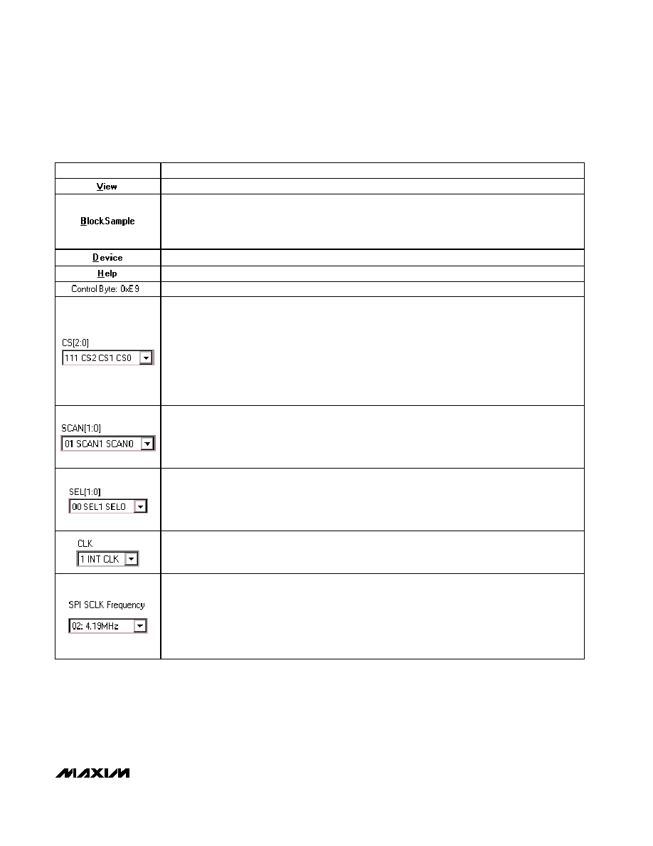
CONTROL
DESCRIPTION
The View menu makes the COM port debug form visible
The BlockSample menu is an EV kit software feature that allows a single channel to be sampled and
stored. The data block length is selectable and the data can be saved to a file. Block sampling is limited
to single-channel read modes only. SCAN[1:0] = 01 or 11 modes are not supported. For multiple-channel
reads, use the Read ADC button or the AutoRead checkbox.
The Device menu allows the user to evaluate either the MAX1168 or MAX1068
The Help menu allows the user to view the help file or the software's about box
The Control Byte label shows the current control byte setting in hexadecimal
The CS[2:0] combobox selects the channel below:
000 CS2 CS1 CS0 = Channel 0
001 CS2 CS1 CS0 = Channel 1
010 CS2 CS1 CS0 = Channel 2
011 CS2 CS1 CS0 = Channel 3
100 CS2 CS1 CS0 = Channel 4
101 CS2 CS1 CS0 = Channel 5
110 CS2 CS1 CS0 = Channel 6
111 CS2 CS1 CS0 = Channel 7
The SCAN[1:0] combobox selects the scan mode below:
00 SCAN1 SCAN0 = Single channel, no scan
01 SCAN1 SCAN0 = Sequentially scans channel 0 to CS[2:0]
10 SCAN1 SCAN0 = Sequentially scans channel 4 to CS[2:0]; CS[2:0]
4
11 SCAN1 SCAN0 = Scan channel CS[2:0] eight times
The SEL[1:0] combobox selects the reference mode below:
00 SEL1 SEL0 = Internal reference mode
01 SEL1 SEL0 = EV kit software does not support this mode
10 SEL1 SEL0 = EV kit software does not support this mode
11 SEL1 SEL0 = External reference mode
The CLK combobox selects the clock mode below:
0 EXT CLK
1 INT CLK
The SPI SCLK Frequency combobox selections are:
02: 4.19MHz
04: 2.10MHz
.
.
.
FF: 33kHz
Evaluates: MAX1068/MAX1168
MAX1168 Evaluation Kit/Evaluation System
_______________________________________________________________________________________
3
Table 1. Software Control Descriptions
Evaluates: MAX1068/MAX1168
MAX1168 Evaluation Kit/Evaluation System
4
_______________________________________________________________________________________
Detailed Description of Hardware
MAX1168 EV System
The MAX1168 EV system is a complete 8-channel, 16-
bit data-acquisition system consisting of a MAX1168 EV
kit and a Maxim 68HC16MODULE-DIP µC module. The
MAX1168 EV system is used to evaluate the MAX1168
8-channel, 16-bit serial ADC. See the Quick Start sec-
tion for setup and operating instructions. See Table 1 for
more information on the provided Windows software.
MAX1168 EV Kit
The MAX1168 EV kit board provides a proven layout for
evaluating the MAX1168 8-channel, 16-bit ADC and can
be obtained separately without the µC module for use
with an existing µC. The MAX1168 EV kit contains two
different types of buffers. U2 is a logic buffer to limit the
load capacitance that is seen by the DOUT line of the
MAX1168. U3≠U10 are 16-bit accurate analog buffers
connected in the unity-gain configuration. U1 is powered
from V
DD
and U3≠U10 are powered from V
DD
and V
EE
.
U3 is powered from the µC module (J1-7, J1-8). A termi-
nal block (TB0) has also been provided on the MAX1168
EV kit board for evaluating external reference mode.
Refer to the MAX1167/MAX1168 or MAX1067/ MAX1068
data sheets to ensure all interface timing specifications
are met.
The MAX1168 and MAX1168 EV kit board support DSP
and 16-bit-wide data-transfer mode. Jumpers JU1 and
JU2 can be configured for these modes; however, the
supplied EV kit Windows-compatible software does not
support these two modes. Please refer to the
MAX1167/MAX1168 or MAX1067/MAX1068 data sheets
for more information.
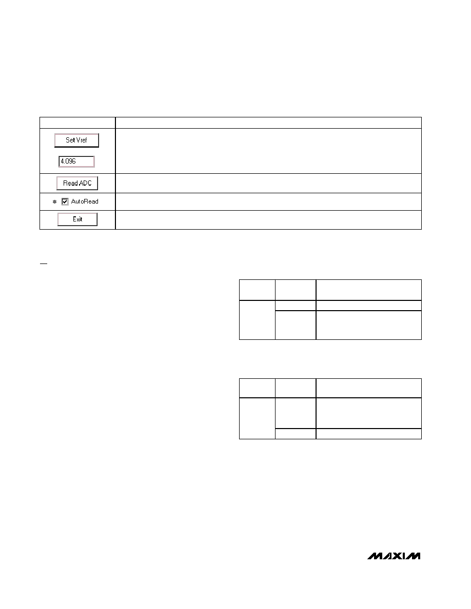
Table 1. Software Control Descriptions (continued)
CONTROL
DESCRIPTION
The Se t Vr e f b utton al l ow s the user to sp eci fy the actual r efer ence vol tag e. The eval uati on softw ar e
assum es a + 4.096V r efer ence vol tag e, unl ess other w i se sp eci fi ed . To over r i d e the d efaul t + 4.096V softw ar e
r efer ence val ue, m easur e the actual r efer ence vol tag e at the ter m i nal b l ock ( TB0) on the M AX 1168 E V ki t
b oar d and enter the new r efer ence vol tag e, w i thout the vol t uni t. Fi nal l y, p r ess the Se t Vr e f b utton. The E V ki t
softw ar e uses the val ue typ ed i n the V r ef fi el d to tr ansl ate the d i g i tal cod e to a vol tag e.
Pressing the Read ADC button performs the conversion(s) specified by the control byte and reads back
the result(s).
Checking the AutoRead checkbox performs the conversion(s) specified by the control byte and reads
back the result(s) every 500ms. A blinking asterisk indicates AutoRead is active.
The Exit button closes the program
Table 2. DSP Frame Sync Receive Input
(DSPR)
JUMPER
SHUNT
POSITION
DESCRIPTION
ON*
DSP mode disable
JU1
OFF
DSP mode enable (the supplied
Windows software does not
support this mode)
Table 3. Data Bit Transfer Select Input
(DSEL)
JUMPER
SHUNT
POSITION
DESCRIPTION
1≠2
16-bit-wide data-transfer mode
(the supplied Windows software
does not support this mode)
JU2
2≠3*
8-bit-wide data-transfer mode
Caution: Do not connect an external controller to
the DSEL pad while a shunt is on jumper JU2.
*Default configuration.
*Default configuration.

Evaluates: MAX1068/MAX1168
MAX1168 Evaluation Kit/Evaluation System
_______________________________________________________________________________________
5
Figure 1. MAX1168 Evaluation Software's Main Window