 | –≠–ª–µ–∫—Ç—Ä–æ–Ω–Ω—ã–π –∫–æ–º–ø–æ–Ω–µ–Ω—Ç: MAX6440UT | –°–∫–∞—á–∞—Ç—å:  PDF PDF  ZIP ZIP |
General Description
The MAX6439≠MAX6442 are a family of ultra-low-power
battery monitors with integrated microprocessor (µP)
supervisors. The battery monitors are offered with sin-
gle or dual low-battery output options that can be used
to signal when the battery is OK (enabling full system
operation), when the battery is low (for low-power sys-
tem operation), and when the battery is dead (to dis-
able system operation). These devices also have an
independent µP supervisor that monitors V
CC
and pro-
vides an active-low reset output. A manual reset func-
tion is available to reset the µP with a push-button. No
external components are required.
The MAX6439≠MAX6442 are offered with several facto-
ry-trimmed low-battery threshold combinations ideal for
single-cell lithium-ion (Li+) or multicell alkaline/NiCd/
NiMH applications. When the battery voltage drops
below each specified low threshold, the low-battery out-
puts are asserted to alert the system. When the voltage
rises above the specified high thresholds, the outputs
are deasserted after a 150ms minimum timeout period,
ensuring the voltages have stabilized before power cir-
cuitry is activated or providing microprocessor reset tim-
ing. The low and high thresholds provide hysteresis in
battery-operated systems to eliminate output chattering.
The MAX6439/MAX6440 offer factory-trimmed battery
monitors with a single output. The MAX6441/MAX6442
offer factory-trimmed battery monitors with dual outputs.
All battery monitors have open-drain low-battery outputs.
The MAX6439≠MAX6442 monitor system voltages
(V
CC
) from 1.8V to 3.3V with seven fixed reset threshold
options. Each device is offered with two minimum reset
timeout periods of 150ms or 1200ms. The MAX6439/
MAX6441 are offered with an open-drain RESET output
and the MAX6440/MAX6442 are offered with a push-
pull RESET output.
The MAX6439≠MAX6442 are offered in a SOT23 pack-
age and are fully specified over a -40∞C to +85∞C temp-
erature range.
Applications
Battery-Powered Systems (Single-Cell Li+ or
Two-/Three-Cell NiMH, NiCd, Alkaline)
Cell Phones/Cordless Phones
Portable Medical Devices
Electronic Toys
Pagers
PDAs
MP3 Players
Features
o Factory-Trimmed V
BATT
Threshold Options for
Monitoring Single-Cell Li+ or Multicell
Alkaline/NiCd/NiMH Applications
o Immune to Short Battery Voltage Transients
o Low Current (2.5µA typ at 3.6V)
o Single and Dual Low-Battery Output Options
o 150ms Minimum LBO Timeout Period
o Independent µP Reset with Manual Reset
o Factory-Set Reset Thresholds for Monitoring V
CC
from 1.8V to 3.3V
o Available with 150ms (min) and 1.2s (min) V
CC
Reset Timeout Period Options
o -40∞C to +85∞C Operating Temperature Range
o Small 6- and 8-Pin SOT23 Packages
o No External Components
MAX6439≠MAX6442
Low-Power, Single-/Dual-Level Battery Monitors
with Hysteresis and Integrated µP Reset
________________________________________________________________ Maxim Integrated Products
1
MR
RESET
LBO
1
6
V
CC
5
GND
V
BATT
MAX6439
MAX6440
SOT23-6
TOP VIEW
2
3
4
Pin Configurations
Ordering Information
19-2535; Rev 0; 7/02
For pricing, delivery, and ordering information, please contact Maxim/Dallas Direct! at
1-888-629-4642, or visit Maxim's website at www.maxim-ic.com.
PART
TEMP RANGE
PIN-PACKAGE
MAX6439UT_ _ _D_-T
-40∞C to +85∞C
6 SOT23-6
MAX6440UT_ _ _D_-T
-40∞C to +85∞C
6 SOT23-6
MAX6441KA_ _ _D_-T
-40∞C to +85∞C
8 SOT23-8
MAX6442KA_ _ _D_-T
-40∞C to +85∞C
8 SOT23-8
Note: The first two "_ _" are placeholders for the battery moni-
tor voltage levels. Desired threshold levels are set by the part
number suffix found in Tables 1 and 2. The third "_" is the V
CC
reset threshold level suffix found in Table 3. The "_" after the D
is a placeholder for the reset timeout period suffix found in
Table 4. All devices are available in tape-and-reel only. There
is a 2500-piece minimum order increment for standard ver-
sions. Sample stock is typically held on standard versions only.
Nonstandard versions require a minimum order increment of
10,000 pieces. Contact factory for availability.
Pin Configurations continued at end of data sheet.
MAX6439≠MAX6442
Low-Power, Single-/Dual-Level Battery Monitors
with Hysteresis and Integrated µP Reset
2
_______________________________________________________________________________________
ABSOLUTE MAXIMUM RATINGS
Stresses beyond those listed under "Absolute Maximum Ratings" may cause permanent damage to the device. These are stress ratings only, and functional
operation of the device at these or any other conditions beyond those indicated in the operational sections of the specifications is not implied. Exposure to
absolute maximum rating conditions for extended periods may affect device reliability.
*Applying 7V for a duration of 1ms does not damage the device.
V
BATT
, V
CC
to GND.................................................-0.3V to +6V*
Open-Drain LBO, LBOH, LBOL, LBOLH to GND ...-0.3V to +6V*
Open-Drain RESET to GND ....................................-0.3V to +6V*
Push-Pull RESET to GND............................-0.3V to (V
CC
+ 0.3V)
MR to GND .................................................-0.3V to (V
CC
+ 0.3V)
Input/Output Current, All Pins .............................................20mA
Continuous Power Dissipation (T
A
= +70∞C)
6-Pin SOT23 (derate 8.7mW/∞C above +70∞C)............695mW
8-Pin SOT23 (derate 8.9mW/∞C above +70∞C)............714mW
Operating Temperature Range .......................... -40∞C to +85∞C
Junction Temperature ......................................................+150∞C
Storage Temperature Range .............................-65∞C to +150∞C
Lead Temperature (soldering, 10s) .................................+300∞C
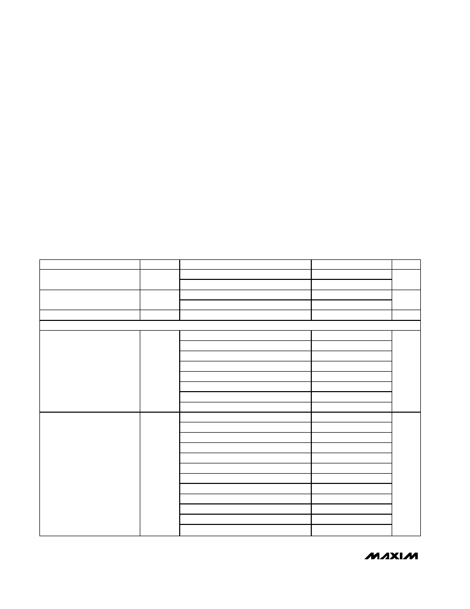
ELECTRICAL CHARACTERISTICS
(V
BATT
= 1.2V to 5.5V, V
CC
= 1.2V to 5.5V, T
A
= -40∞C to +85∞C, unless otherwise specified. Typical values are at T
A
= +25∞C.) (Note1)
PARAMETER
SYMBOL
CONDITIONS
MIN
TYP
MAX
UNITS
T
A
= 0∞C to +85∞C
1.0
5.5
V
BATT
Operating Voltage Range
V
BATT
T
A
= -40∞C to +85∞C
1.2
5.5
V
T
A
= 0∞C to +85∞C
1.0
5.5
V
CC
Operating Voltage Range
V
CC
T
A
= -40∞C to +85∞C
1.2
5.5
V
V
CC
+ V
BATT
Supply Current
I
CC
+ I
BATT
V
BATT
= 3.6V, V
CC
= 3.3V, no load (Note 2)
2.5
7
µA
V
BATT
THRESHOLDS
MAX6439UT_ J, MAX6440UT_ J
3.510
3.60
3.690
MAX6439UT_ I, MAX6440UT_ I
3.413
3.50
3.588
MAX6439UT_ H, MAX6440UT_ H
3.315
3.40
3.485
MAX6439UT_ G, MAX6440UT_ G
3.218
3.30
3.383
MAX6439UT_ T, MAX6440UT_ T
2.535
2.60
2.665
MAX6439UT_ S, MAX6440UT_ S
2.438
2.50
2.563
MAX6439UT_ R, MAX6440UT_ R
2.340
2.40
2.460
HTH Threshold
HTH
MAX6439UT_ Q, MAX6440UT_ Q
2.243
2.30
2.358
V
MAX6439UTF, MAX6440UTF
3.023
3.10
3.178
MAX6439UTE, MAX6440UTE
2.925
3.00
3.075
MAX6439UTD, MAX6440UTD
2.828
2.90
2.973
MAX6439UTC, MAX6440UTC
2.730
2.80
2.870
MAX6439UTB, MAX6440UTB
2.633
2.70
2.768
MAX6439UTA, MAX6440UTA
2.535
2.60
2.665
MAX6439UTP, MAX6440UTP
2.048
2.10
2.153
MAX6439UTO, MAX6440UTO
1.950
2.00
2.050
MAX6439UTN, MAX6440UTN
1.853
1.90
1.948
MAX6439UTM, MAX6440UTM
1.755
1.80
1.845
MAX6439UTL, MAX6440UTL
1.658
1.70
1.743
LTH Threshold
LTH
MAX6439UTK, MAX6440UTK
1.560
1.60
1.640
V
MAX6439≠MAX6442
Low-Power, Single-/Dual-Level Battery Monitors
with Hysteresis and Integrated µP Reset
_______________________________________________________________________________________
3
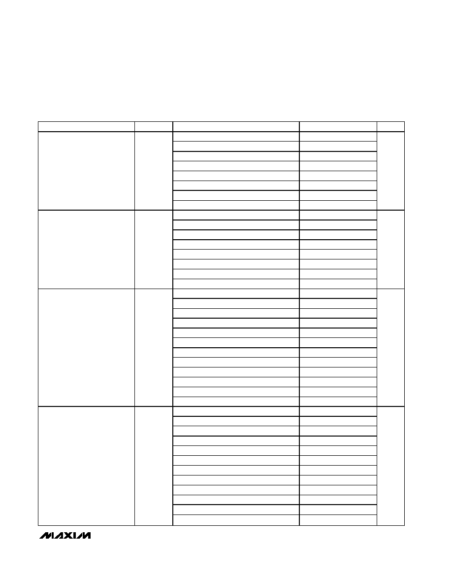
ELECTRICAL CHARACTERISTICS (continued)
(V
BATT
= 1.2V to 5.5V, V
CC
= 1.2V to 5.5V, T
A
= -40∞C to +85∞C, unless otherwise specified. Typical values are at T
A
= +25∞C.) (Note1)
PARAMETER
SYMBOL
CONDITIONS
MIN
TYP
MAX
UNITS
MAX6441UT_ J, MAX6442UT_ J
3.510
3.600
3.690
MAX6441UT_ I, MAX6442UT_ I
3.413
3.500
3.588
MAX6441UT_ H, MAX6442UT_ H
3.315
3.400
3.485
MAX6441UT_ G, MAX6442UT_ G
3.218
3.300
3.383
MAX6441UT_ T, MAX6442UT_ T
2.535
2.600
2.665
MAX6441UT_ S, MAX6442UT_ S
2.438
2.500
2.563
MAX6441UT_ R, MAX6442UT_ R
2.340
2.400
2.460
HTH- Threshold
HTH-
MAX6441UT_ Q, MAX6442UT_ Q
2.243
2.300
2.358
V
MAX6441UT_ J, MAX6442UT_ J
3.686
3.780
3.875
MAX6441UT_ I, MAX6442UT_ I
3.583
3.675
3.767
MAX6441UT_ H, MAX6442UT_ H
3.481
3.570
3.659
MAX6441UT_ G, MAX6442UT_ G
3.378
3.465
3.552
MAX6441UT_ T, MAX6442UT_ T
2.662
2.730
2.798
MAX6441UT_ S, MAX6442UT_ S
2.559
2.625
2.691
MAX6441UT_ R, MAX6442UT_ R
2.457
2.520
2.583
HTH+ Threshold
HTH+
MAX6441UT_ Q, MAX6442UT_ Q
2.355
2.415
2.476
V
MAX6441UTF, MAX6442UTF
3.023
3.100
3.178
MAX6441UTE, MAX6442UTE
2.925
3.000
3.075
MAX6441UTD, MAX6442UTD
2.828
2.900
2.973
MAX6441UTC, MAX6442UTC
2.730
2.800
2.870
MAX6441UTB, MAX6442UTB
2.633
2.700
2.768
MAX6441UTA, MAX6442UTA
2.535
2.600
2.665
MAX6441UTP, MAX6442UTP
2.048
2.100
2.153
MAX6441UTO, MAX6442UTO
1.950
2.000
2.050
MAX6441UTN, MAX6442UTN
1.853
1.900
1.948
MAX6441UTM, MAX6442UTM
1.755
1.800
1.845
MAX6441UTL, MAX6442UTL
1.658
1.700
1.743
LTH- Threshold
LTH-
MAX6441UTK, MAX6442UTK
1.560
1.600
1.640
V
MAX6441UTF, MAX6442UTF
3.174
3.255
3.337
MAX6441UTE, MAX6442UTE
3.071
3.150
3.229
MAX6441UTD, MAX6442UTD
2.969
3.045
3.121
MAX6441UTC, MAX6442UTC
2.867
2.940
3.014
MAX6441UTB, MAX6442UTB
2.764
2.835
2.906
MAX6441UTA, MAX6442UTA
2.662
2.730
2.798
MAX6441UTP, MAX6442UTP
2.150
2.205
2.260
MAX6441UTO, MAX6442UTO
2.048
2.100
2.153
MAX6441UTN, MAX6442UTN
1.945
1.995
2.045
MAX6441UTM, MAX6442UTM
1.843
1.890
1.937
MAX6441UTL, MAX6442UTL
1.740
1.785
1.830
LTH+ Threshold
LTH+
MAX6441UTK, MAX6442UTK
1.638
1.680
1.722
V
MAX6439≠MAX6442
Low-Power, Single-/Dual-Level Battery Monitors
with Hysteresis and Integrated µP Reset
4
_______________________________________________________________________________________
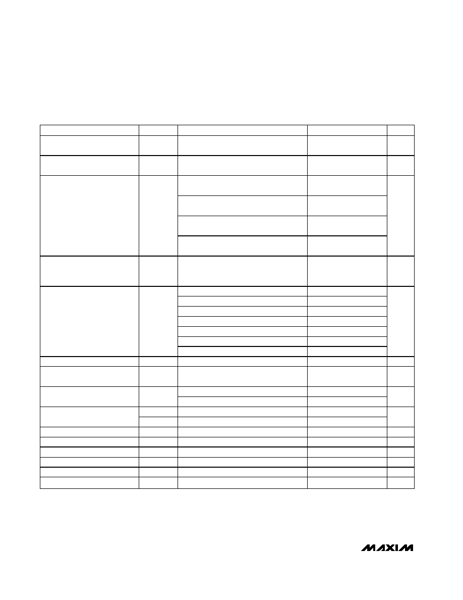
ELECTRICAL CHARACTERISTICS (continued)
(V
BATT
= 1.2V to 5.5V, V
CC
= 1.2V to 5.5V, T
A
= -40∞C to +85∞C, unless otherwise specified. Typical values are at T
A
= +25∞C.) (Note1)
PARAMETER
SYMBOL
CONDITIONS
MIN
TYP
MAX
UNITS
LBO, LBOL, LBOH, LBOLH
Timeout Period
t
LBOP
V
BATT
rising above threshold
150
225
300
ms
LBO, LBOL, LBOH, LBOLH
Delay Time
t
LBOD
V
BATT
falling below threshold
100
µs
(V
BATT
or V
CC
)
1.2V, I
SINK
= 50µA,
asserted low
0.3
(V
BATT
or V
CC
)
1.6V, I
SINK
= 100µA,
asserted low
0.3
(V
BATT
or V
CC
)
2.7V, I
SINK
= 1.2mA,
asserted low
0.3
LBO, LBOL, LBOH, LBOLH
Output Low
(Open Drain)
V
OL
(V
BATT
or V
CC
)
4.5V, I
SINK
= 3.2mA,
asserted low
0.3
V
LBO, LBOL, LBOH, LBOLH
Output Open-Drain Leakage
Current
I
LKG
Output deasserted
500
nA
MAX64_ _ _ _ _ _ T
3.000
3.075
3.150
MAX64_ _ _ _ _ _ S
2.850
2.925
3.000
MAX64_ _ _ _ _ _ R
2.550
2.625
2.700
MAX64_ _ _ _ _ _ Z
2.250
2.313
2.375
MAX64_ _ _ _ _ _ Y
2.125
2.188
2.250
MAX64_ _ _ _ _ _ W
1.620
1.665
1.710
V
CC
Reset Threshold
V
TH
MAX64_ _ _ _ _ _ V
1.530
1.575
1.620
V
V
CC
Reset Hysteresis
0.3
%
V
CC
to RESET Delay
V
CC
falling at 10mV/µs from (V
TH
+ 100mV)
to (V
TH
- 100mV)
50
µs
MAX64_ _ _ _ _ _ _ D3
150
225
300
V
CC
to RESET Timeout Period
t
RP
MAX64_ _ _ _ _ _ _ D7
1200
1800
2400
ms
V
IL
0.3 x V
CC
MR Input Voltage
V
IH
0.7 x V
CC
V
MR Minimum Pulse Width
t
MPW
1
µs
MR Glitch Rejection
100
ns
MR to RESET Delay
200
ns
MR Reset Timeout Period
t
MRP
150
225
300
ms
MR Pullup Resistance
MR to V
CC
750
1500
2250
MR Rising Debounce Period
t
DEB
(Note 3)
150
225
300
ms
MAX6439≠MAX6442
Low-Power, Single-/Dual-Level Battery Monitors
with Hysteresis and Integrated µP Reset
_______________________________________________________________________________________
5
ELECTRICAL CHARACTERISTICS (continued)
(V
BATT
= 1.2V to 5.5V, V
CC
= 1.2V to 5.5V, T
A
= -40∞C to +85∞C, unless otherwise specified. Typical values are at T
A
= +25∞C.) (Note1)
PARAMETER
SYMBOL
CONDITIONS
MIN
TYP
MAX
UNITS
V
CC
1.53V, I
SOURCE
= 100µA, RESET
deasserted
0.8 x V
CC
RESET Output High
(Push-Pull)
V
OH
V
CC
2.55V, I
SOURCE
= 500µA, RESET
deasserted
0.8 x V
CC
V
V
CC
1.0V, I
SINK
= 50µA, RESET asserted
0.3
V
CC
1.2V, I
SINK
= 100µA, RESET asserted
0.3
RESET Output Low
V
OL
V
CC
2.12V, I
SINK
= 1.2mA, RESET
asserted
0.3
V
RESET Output Leakage Current
(Open Drain)
RESET deasserted
500
nA
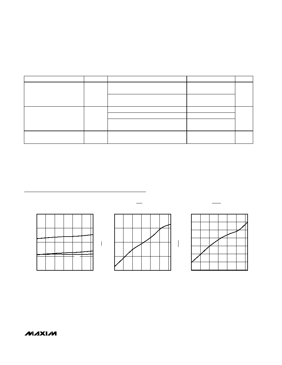
Typical Operating Characteristics
(V
BATT
= 1.2V to 5.5V, V
CC
= 1.2V to 5.5V, unless otherwise specified. Typical values are at T
A
= +25∞C.)
SUPPLY CURRENT vs. TEMPERATURE
V
CC
= 3.3V, V
BATT
= 3.6V
MAX6439 toc01
TEMPERATURE (
∞C)
TOTAL
I
BATT
SUPPLY CURRENT (
µ
A)
60
40
20
0
-20
1
2
3
4
0
-40
80
I
CC
NORMALIZED LBO TIMEOUT PERIOD
vs. TEMPERATURE
MAX6439 toc02
TEMPERATURE (
∞C)
NORMALIZED LBO TIMEOUT PERIOD
60
40
20
0
-20
0.95
1.00
1.05
1.10
0.90
-40
80
NORMALIZED RESET TIMEOUT PERIOD
vs. TEMPERATURE
MAX6439 toc03
TEMPERATURE (
∞C)
NORMALIZED RESET TIMEOUT PERIOD
60
40
20
0
-20
0.990
0.985
1.000
0.995
1.005
1.010
1.015
0.980
-40
80
Note 1: Production testing done at T
A
= +25∞C; limits over temperature guaranteed by design only.
Note 2: The device is powered up by the highest voltage between V
BATT
and V
CC
.
Note 3: MR input ignores falling input pulses, which occur within the MR debounce period (t
DEB
) after a valid MR reset assertion.
This prevents invalid reset assertion due to switch bounce.