General Description
The MAX6754≠MAX6764 low-power window detectors
monitor undervoltage/overvoltage conditions on system
power supplies. These devices assert when the moni-
tored voltage is under the undervoltage and/or over the
overvoltage thresholds.
The MAX6754≠MAX6759/MAX6763/MAX6764 monitor a
single voltage. The MAX6760/MAX6761/MAX6762
monitor dual-voltage systems. The MAX6754/MAX6755/
MAX6756 provide a single undervoltage/overvoltage
output and the MAX6757≠MAX6764 provide indepen-
dent undervoltage and overvoltage outputs. The out-
puts are available in push-pull or open-drain
configurations.
The MAX6754≠MAX6762 offer factory-fixed voltage
thresholds for monitoring system voltages from 0.9V to
5V with a selectable ±5%, ±10%, or ±15% window volt-
age. The MAX6763/MAX6764 allow for externally
adjustable thresholds. The MAX6754≠MAX6762 are
available in two delay timing options (20µs, typ or
100ms, min). The MAX6760/MAX6761/MAX6762 also
include a latched overvoltage output function and the
MAX6754≠MAX6762 include a manual reset input.
The family of products is available in small SOT23 and
TDFN packages and is specified over the extended
temperature range of -40∞C to +125∞C.
Applications
Features
Single- or Dual-Supply Voltage Monitors
Factory-Trimmed Window Threshold Options for
5V, 3.3V, 3V, 2.5V, 1.8V, 1.5V, 1.2V, and 0.9V
Supplies
Externally Adjustable Window Monitoring Options
for Supplies Down to 0.5V
Selectable Window Threshold Options (±5%,
±10%, ±15%)
Single (Combined UV/OV) or Dual (Separate UV
and OV) Outputs
20µs (typ) or 100ms (min) Timeout Period Options
(MAX6754≠MAX6762)
Manual Reset Input (MAX6754≠MAX6762)
Latched Overvoltage Output Function
(MAX6760/MAX6761/MAX6762)
Immune to Short Voltage Transients
Low 10µA Supply Current
Low-Voltage Operation (Outputs Valid for V
CC
Down to 1V)
-40∞C to +125∞C Operating Temperature Range
Small SOT23 and TDFN Packages
MAX6754≠MAX6764
Low-Power, Single/Dual-Voltage Window
Detectors
________________________________________________________________ Maxim Integrated Products
1
Ordering Information
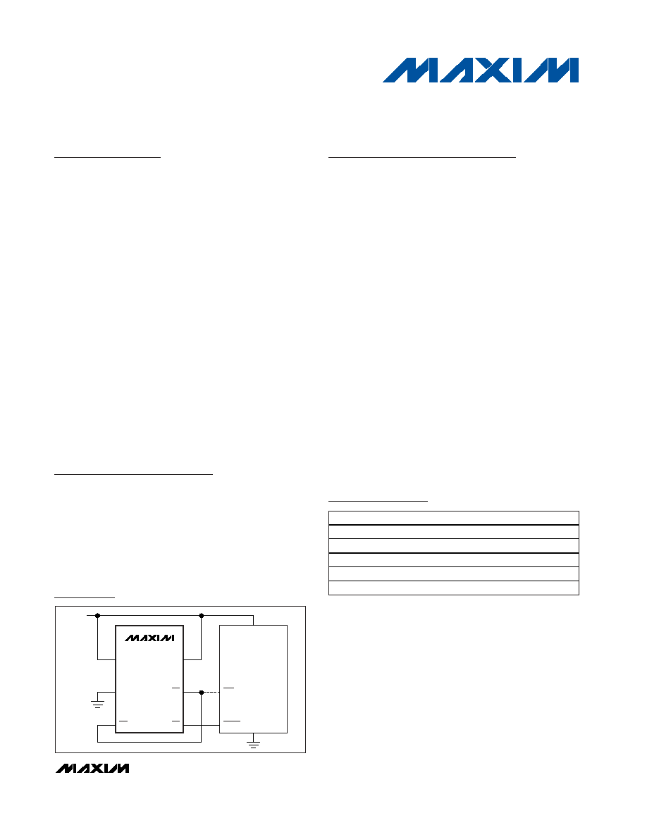
MAX6757
NMI
RESET
MR
GND
V
CC
UV
OV
SET
V
CC
µP
Typical Application Circuit
19-3075; Rev 2; 4/04
For pricing, delivery, and ordering information, please contact Maxim/Dallas Direct! at
1-888-629-4642, or visit Maxim's website at www.maxim-ic.com.
PART*
TEMP RANGE
PIN-PACKAGE
MAX6754
UK_D_-T
-40∞C to +125∞C
5 SOT23-5
MAX6755
UK_D_-T
-40∞C to +125∞C
5 SOT23-5
MAX6756
UK_D_-T
-40∞C to +125∞C
5 SOT23-5
MAX6757
UT_D_-T
-40∞C to +125∞C
6 SOT23-6
MAX6758
UT_D_-T
-40∞C to +125∞C
6 SOT23-6
*
Note:
Insert the threshold level suffixes for V
CC
and V
CC2
(Tables 1 and 2) after UK, UT, or TA. For the
MAX6754≠MAX6759, insert only the V
CC
threshold suffix after
the UK or UT. Insert the reset timeout delay (
Table
3) after D to
complete the part number. For example, the MAX6760TALTD3-T
provides a V
CC
threshold of 5V, a V
CC2
threshold of 3.3V, and a
100ms minimum reset timeout period. Sample stock is generally
held on standard versions only (see the Standard Versions
table
). Standard versions have an order increment requirement
of 2500 pieces. Nonstandard versions have an order increment
requirement of 10,000 pieces. Contact factory for availability.
Ordering Information continued at end of data sheet.
Pin Configurations appear at end of data sheet.
Telecommunications
Networking
Computers/Servers
Data Storage
Power Metering
DC-DC Converter
Modules
Automotive
MAX6754≠MAX6764
Low-Power, Single/Dual-Voltage Window
Detectors
2
_______________________________________________________________________________________
ABSOLUTE MAXIMUM RATINGS
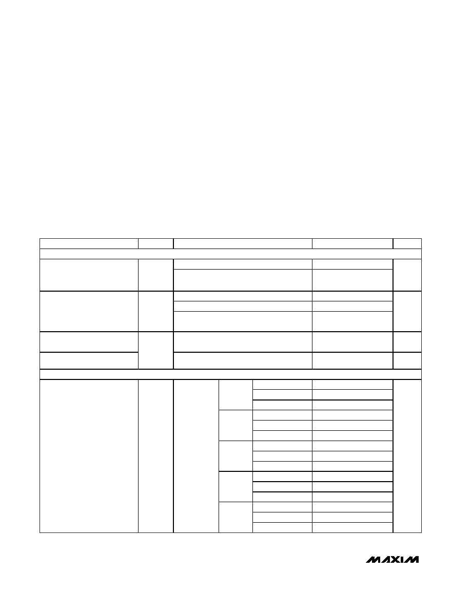
ELECTRICAL CHARACTERISTICS
(V
CC
= 1.0V to 6.0V, V
CC2
= 0 to 6.0V (MAX6760≠MAX6762), T
A
= -40∞C to +125∞C, unless otherwise noted. Typical values are at T
A
=
+25∞C.) (Note 1)
Stresses beyond those listed under "Absolute Maximum Ratings" may cause permanent damage to the device. These are stress ratings only, and functional
operation of the device at these or any other conditions beyond those indicated in the operational sections of the specifications is not implied. Exposure to
absolute maximum rating conditions for extended periods may affect device reliability.
(Voltages with respect to GND)
V
CC
, V
CC2
, ............................................................-0.3V to +6.5V
SET, OVLATCH,
MR, UVIN, OVIN ..............-0.3V to (V
CC
+ 0.3V)
UV, RESET, OV (open drain) .................................-0.3V to +6.5V
RESET, OV, UV, UV, RESET (push-pull).....-0.3V to (V
CC
+ 0.3V)
Input/Output Current (all pins) ............................................20mA
Continuous Power Dissipation (T
A
= +70∞C)
5-Pin SOT23-5 (derate 7.1mW/∞C above T
A
= +70∞C)....571mW
6-Pin SOT23-6 (derate 8.7mW/∞C above T
A
= +70∞C)....696mW
8-Pin TDFN (derate 24.4mW/∞C above T
A
= +70∞C).....1951mW
Operating Temperature Range .........................-40∞C to +125∞C
Junction Temperature ......................................................+150∞C
Storage Temperature Range .............................-65∞C to +150∞C
Lead Temperature (soldering, 10s) .................................+300∞C
PARAMETER
SYMBOL
CONDITIONS
MIN
TYP
MAX
UNITS
POWER REQUIREMENTS
(Note 2)
1.0
6.0
Operating Voltage Range
V
CC
MAX6760TAAA/MAX6761TAAA/
MAX6762TAAA/MAX6763/MAX6764UT-T
1.4
6.0
V
V
CC
= 3.6V, MAX6754≠MAX6759, no load
13
30
V
CC
= 3.6V, MAX6763/MAX6764, no load
10
23
V
CC
Supply Current
I
CC
V
CC
= 3.6V, V
CC
V
CC2
,
MAX6760/MAX6761/MAX6762, no load
13
30
µA
V
CC2
Supply Current
V
CC2
= 1.8V, V
CC
V
CC2
,
MAX6760/MAX6761/MAX6762
1
1.5
µA
Adjustable Bias Current
I
CC2
V
CC2
(MAX6760≠MAX6762TA_AD_)
(Note 3)
-20
+20
nA
V
CC
THRESHOLD
V
SET
= V
SB
5.750
5.875
6.000
SET = V
CC
5.500
5.625
5.750
L, 5V
SET = GND
5.250
5.375
5.500
V
SET
= V
SB
3.795
3.878
3.960
SET = V
CC
3.630
3.713
3.795
T, 3.3V
SET = GND
3.465
3.548
3.630
V
SET
= V
SB
3.450
3.525
3.600
SET = V
CC
3.300
3.375
3.450
R, 3.0V
SET = GND
3.150
3.225
3.300
V
SET
= V
SB
2.875
2.938
3.000
SET = V
CC
2.750
2.813
2.875
Z, 2.5V
SET = GND
2.625
2.688
2.750
V
SET
= V
SB
2.070
2.115
2.160
SET = V
CC
1.980
2.025
2.070
V
CC
Overvoltage Threshold
OV
TH
T
A
= -40∞C to
+125∞C,
rising V
CC
W, 1.8V
SET = GND
1.890
1.935
1.980
V
MAX6754≠MAX6764
Low-Power, Single/Dual-Voltage Window
Detectors
_______________________________________________________________________________________
3
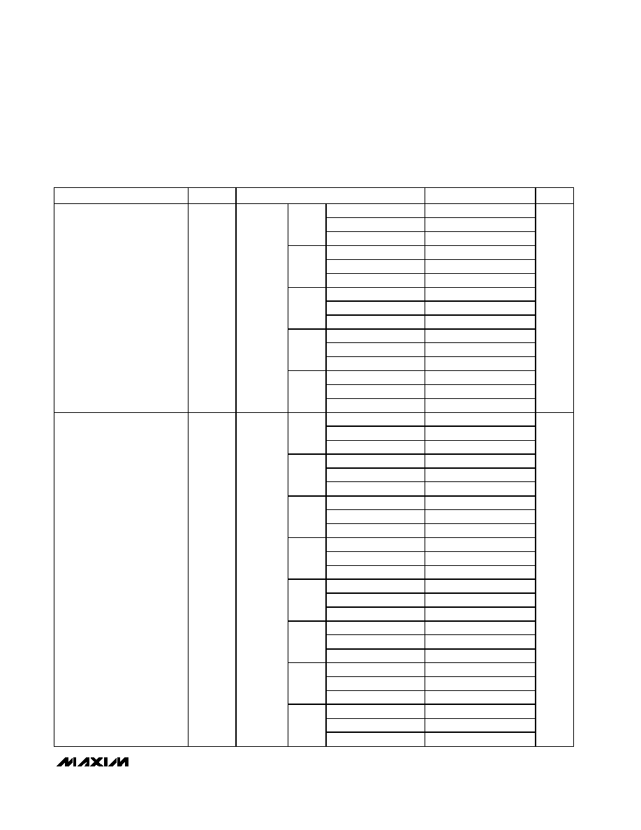
ELECTRICAL CHARACTERISTICS (continued)
(V
CC
= 1.0V to 6.0V, V
CC2
= 0 to 6.0V (MAX6760≠MAX6762), T
A
= -40∞C to +125∞C, unless otherwise noted. Typical values are at T
A
=
+25∞C.) (Note 1)
PARAMETER
SYMBOL
CONDITIONS
MIN
TYP
MAX
UNITS
V
SET
= V
SB
4.000
4.125
4.250
SET = V
CC
4.250
4.375
4.500
L, 5V
SET = GND
4.500
4.625
4.750
V
SET
= V
SB
2.640
2.723
2.805
SET = V
CC
2.805
2.888
2.970
T, 3.3V
SET = GND
2.970
3.053
3.135
V
SET
= V
SB
2.400
2.475
2.550
SET = V
CC
2.550
2.625
2.700
R, 3.0V
SET = GND
2.700
2.775
2.850
V
SET
= V
SB
2.000
2.063
2.125
SET = V
CC
2.125
2.188
2.250
Z, 2.5V
SET = GND
2.250
2.313
2.375
V
SET
= V
SB
1.440
1.485
1.530
SET = V
CC
1.530
1.575
1.620
V
CC
Undervoltage Threshold
UV
TH
T
A
= -40∞C
to +125∞C,
falling V
CC
W, 1.8V
SET = GND
1.620
1.665
1.710
V
V
SET
= V
SB
3.795
3.878
3.960
SET = V
CC
3.630
3.713
3.795
T, 3.3V
SET = GND
3.465
3.548
3.630
V
SET
= V
SB
3.450
3.525
3.600
SET = V
CC
3.300
3.375
3.450
R, 3.0V
SET = GND
3.150
3.225
3.300
V
SET
= V
SB
2.875
2.938
3.000
SET = V
CC
2.750
2.813
2.875
Z, 2.5V
SET = GND
2.625
2.688
2.750
V
SET
= V
SB
2.070
2.115
2.160
SET = V
CC
1.980
2.025
2.070
W, 1.8V
SET = GND
1.890
1.935
1.980
V
SET
= V
SB
(Note 2)
1.725
1.763
1.800
SET = V
CC
(Note 2)
1.650
1.688
1.725
I, 1.5V
SET = GND (Note 2)
1.575
1.613
1.650
V
SET
= V
SB
(Note 2)
1.380
1.410
1.440
SET = V
CC
(Note 2)
1.320
1.350
1.380
G, 1.2V
SET = GND (Note 2)
1.260
1.290
1.320
V
SET
= V
SB
(Note 2)
1.035
1.058
1.080
SET = V
CC
(Note 2)
0.990
1.013
1.035
E, 0.9V
SET = GND (Note 2)
0.945
0.968
0.990
V
SET
= V
SB
0.489
0.500
0.511
SET = V
CC
0.468
0.479
0.489
V
CC2
Overvoltage Threshold
OV
TH2
T
A
= -40∞C
to +125∞C,
rising V
CC2
ADJ
SET = GND
0.447
0.457
0.468
V
MAX6754≠MAX6764
Low-Power, Single/Dual-Voltage Window
Detectors
4
_______________________________________________________________________________________
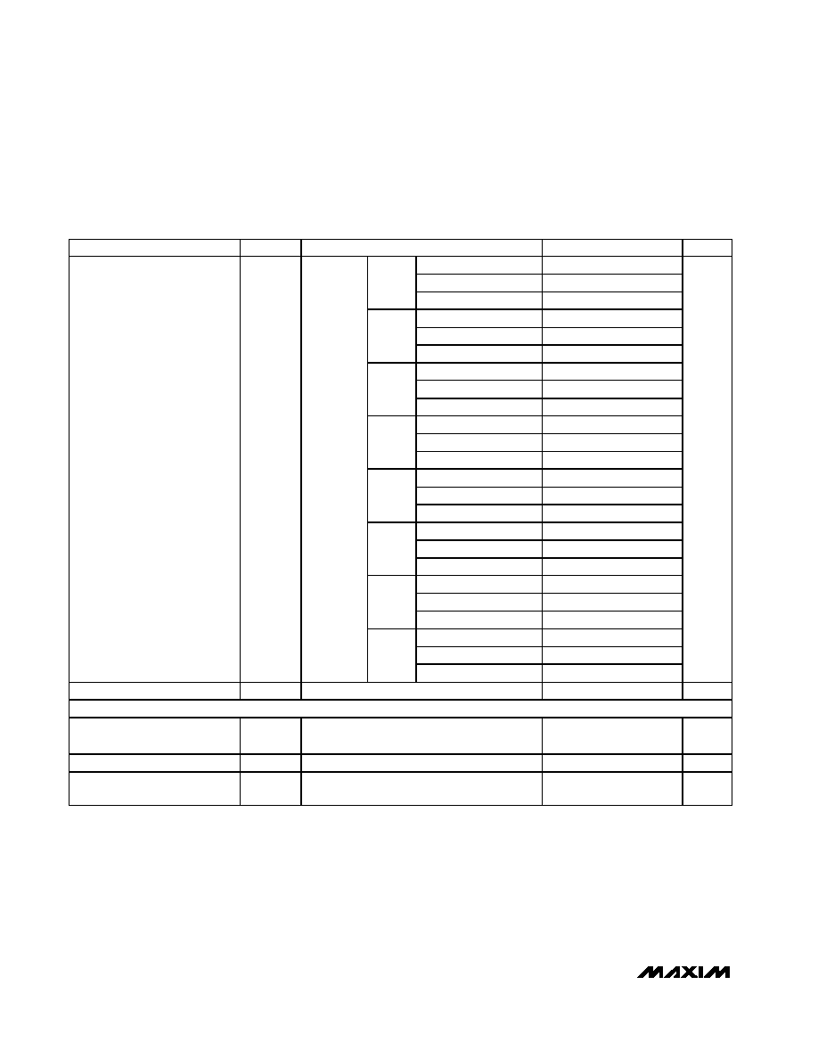
ELECTRICAL CHARACTERISTICS (continued)
(V
CC
= 1.0V to 6.0V, V
CC2
= 0 to 6.0V (MAX6760≠MAX6762), T
A
= -40∞C to +125∞C, unless otherwise noted. Typical values are at T
A
=
+25∞C.) (Note 1)
PARAMETER
SYMBOL
CONDITIONS
MIN
TYP
MAX
UNITS
V
SET
= V
SB
2.640
2.723
2.805
SET = V
CC
2.805
2.888
2.970
T, 3.3V
SET = GND
2.970
3.053
3.135
V
SET
= V
SB
2.400
2.475
2.550
SET = V
CC
2.550
2.625
2.700
R, 3.0V
SET = GND
2.700
2.775
2.850
V
SET
= V
SB
2.000
2.063
2.125
SET = V
CC
2.125
2.188
2.250
Z, 2.5V
SET = GND
2.250
2.313
2.375
V
SET
= V
SB
1.440
1.485
1.530
SET = V
CC
1.530
1.575
1.620
W, 1.8V
SET = GND
1.620
1.665
1.710
V
SET
= V
SB
(Note 2)
1.200
1.238
1.275
SET = V
CC
(Note 2)
1.275
1.313
1.350
I, 1.5V
SET = GND (Note 2)
1.350
1.388
1.425
V
SET
= V
SB
(Note 2)
0.960
0.990
1.020
SET = V
CC
(Note 2)
1.020
1.050
1.080
G, 1.2V
SET = GND (Note 2)
1.080
1.110
1.140
V
SET
= V
SB
(Note 2)
0.720
0.743
0.765
SET = V
CC
(Note 2)
0.765
0.788
0.810
E, 0.9V
SET = GND (Note 2)
0.810
0.833
0.855
V
SET
= V
SB
0.340
0.351
0.362
SET = V
CC
0.362
0.372
0.383
V
CC2
Undervoltage Threshold
UV
TH2
T
A
= -40∞C
to +125∞C,
falling V
CC2
ADJ
SET = GND
0.383
0.394
0.404
V
Threshold Hysteresis
V
HYST
V
CC
, V
CC2
0.7
%
UNDERVOLTAGE/OVERVOLTAGE INPUTS (UVIN, OVIN) (MAX6763/MAX6764)
UVIN, OVIN Threshold Voltage
V
TH-IN
0.485
0.5
0.515
V
UVIN, OVIN Input Bias Current
I
IN
(Note 3)
-20
+20
nA
UVIN, OVIN Threshold
Hysteresis
V
HYST
0.7
%

MAX6754≠MAX6764
Low-Power, Single/Dual-Voltage Window
Detectors
_______________________________________________________________________________________
5
ELECTRICAL CHARACTERISTICS (continued)
(V
CC
= 1.0V to 6.0V, V
CC2
= 0 to 6.0V (MAX6760≠MAX6762), T
A
= -40∞C to +125∞C, unless otherwise noted. Typical values are at T
A
=
+25∞C.) (Note 1)
PARAMETER
SYMBOL
CONDITIONS
MIN
TYP
MAX
UNITS
TIMING CHARACTERISTICS
D0
20
µs
Reset and UV Timeout Period
t
RP
Figure 7
D3
100
185
320
ms
V
CC
to Reset Delay
t
D-RESET
V
CC
/V
CC2
falling at 10mV/µs from
UV
TH
+ 100mV to UV
TH
- 100mV
20
µs
V
CC
to UV Delay
t
D-UV
V
CC
/V
CC2
rising at 10mV/µs from
OV
TH
- 100mV to OV
TH
+ 100mV
20
µs
V
CC
to OV Delay
t
D-OV
V
CC
/V
CC2
rising at 10mV/µs from
OV
TH
- 100mV to OV
TH
+ 100mV
(MAX6757≠MAX6762 only)
20
µs
UVIN to UV Delay
(MAX6763/MAX6764)
20
µs
OVIN to OV Delay
(MAX6763/MAX6764)
20
µs
Startup Delay Time
t
START
D0 options only, OV output (Note 4)
2
ms
THRESHOLD WINDOW SELECT INPUT (SET)
Input Voltage Low
0
0.1
V
V
CC
= 1.4V
0.65
0.75
V
CC
= 3.0V
0.81
2.19
Input Bias Voltage
(Note 5)
V
SB
V
CC
= 6.0V
1.10
4.90
V
Input Voltage High
V
CC
- 0.1
V
CC
V
Input Current
I
SET
-1
+1
µA
MANUAL RESET (
MR
)
Input Voltage Low
0.23 x
V
CC
V
Input Voltage High
0.6 x
V
CC
V
Pullup Resistance to V
CC
26
k
Minimum Pulse Width
4
µs
Transient Immunity
300
ns
t
D-MR
MR falling, Figure 7
300
D0
40
ns
Propagation Delay
t
MR_P
MR rising, Figure 7
D3
100
185
320
ms
OVERVOLTAGE OUTPUT LATCH CONTROL INPUT (OVLATCH)
Input Voltage Low
0.3 x
V
CC
V
Input Voltage High
0.7 x
V
CC
V