 | –≠–ª–µ–∫—Ç—Ä–æ–Ω–Ω—ã–π –∫–æ–º–ø–æ–Ω–µ–Ω—Ç: MAX6795TP | –°–∫–∞—á–∞—Ç—å:  PDF PDF  ZIP ZIP |
General Description
The MAX6791≠MAX6796 ultra-low-quiescent-current,
single-/dual-output linear regulators are ideal for auto-
motive applications. The devices offer a wide 5V to 72V
operating input range, allowing them to withstand auto-
motive load-dump conditions while consuming only
68µA. The MAX6791≠MAX6794 are dual-output regula-
tors capable of supplying up to 150mA per output. The
MAX6795/MAX6796 offer a single output capable of
delivering up to 300mA. These devices offer standard
output-voltage options (5V, 3.3V, 2.5V, or 1.8V) and can
be adjusted to any voltage from 1.8V to 11V. The
MAX6791≠MAX6794 also offer a fixed 5V output.
All devices feature a push-pull or open-drain, active-low
RESET output with a fixed output reset threshold that is
92.5%/87.5% of the regulator output OUT/OUT1. The
reset output asserts low when OUT/OUT1 drops below
the reset threshold and remains low for the fixed or
capacitor-adjustable reset timeout period after
OUT/OUT1 exceeds the reset threshold.
The MAX6791≠MAX6796 provide a watchdog input that
monitors a pulse train from the microprocessor (µP) and
generates reset pulses if the watchdog input remains
high or low for a duration longer than the watchdog
timeout period. All devices are available with either a
fixed watchdog timeout period of 280ms (min) or a peri-
od adjustable with an external capacitor. The
MAX6791/MAX6792 feature a windowed watchdog
timeout period with selectable window ratio. The watch-
dog feature can be disabled.
The MAX6791≠MAX6794 provide dual enable inputs
(ENABLE1 and ENABLE2) that control each regulator
independently. The single-output MAX6795/MAX6796
feature one enable input (ENABLE).
All devices include a hold input (HOLD) that aids the
implementation of a self-holding circuit without requir-
ing external components. Once the regulator is
enabled, setting HOLD low forces the regulator to
remain on even if ENABLE/ENABLE1 is subsequently
set low. Releasing HOLD shuts down the regulator.
The MAX6791≠MAX6796 are available in a small, ther-
mally enhanced TQFN package. The 5mm x 5mm
package dissipates up to 2.7W, supporting continuous
regulator operation during high ambient temperatures,
high battery voltage, and high load-current conditions.
The MAX6791≠MAX6796 are specified for a -40∞C to
+125∞C operating temperature range.
Applications
Automotive
Features
Low 68µA Quiescent Current
Wide 5V to 72V Supply Voltage Range
Output Current
Single Output Up to 300mA
Dual Outputs Up to 150mA per Output
Low Dropout Voltage
420mV (typ) at 100mA (Single)
840mV (typ) at 100mA (Dual)
Fixed Output-Voltage Options: 5V, 3.3V, 2.5V,
1.8V, or Adjustable Output (from 1.8V to 11V)
ENABLE and HOLD Functionality
RESET Output: Open Drain or Push-Pull
Internally Fixed (35µs, 3.125ms, 12.5ms, 50ms, or
200ms) or Capacitor-Adjustable Reset Timeout
Periods
Internally Fixed or Capacitor-Adjustable
Watchdog Timeout Periods
Windowed (Minimum/Maximum) Watchdog Timer
Options (MAX6791/MAX6792)
Watchdog Disable Feature
Thermal, Short-Circuit, and Output Overvoltage
Protection
Fully Specified from -40∞C to +125∞C
Small, Thermally Enhanced, 5mm x 5mm TQFN
MAX6791≠MAX6796
High-Voltage, Micropower, Single/Dual
Linear Regulators with Supervisory Functions
________________________________________________________________ Maxim Integrated Products
1
Ordering Information
19-3875; Rev 0; 11/05
For pricing, delivery, and ordering information, please contact Maxim/Dallas Direct! at
1-888-629-4642, or visit Maxim's website at www.maxim-ic.com.
+Denotes lead-free package.
For tape-and-reel, add a T after the "+." Tape-and-reel are
offered in 2.5k increments. The first placeholder "_" designates
preset output-voltage option and preset reset threshold level;
see Table 1. The second placeholder "_ " designates the reset
timeout period; see Table 2. For example, the MAX6791TPSD3+
indicates a 3.3V output voltage with a reset threshold of 87.5%
at nominal voltage and a 50ms reset timeout period. Samples
are generally held in stock. Nonstandard versions require a 2.5k
minimum order quantity.
EVALUATION KIT
AVAILABLE
PART
TEMP
RANGE
PIN-
PACKAGE
PKG
CODE
M A X6 7 9 1 TP _D _+
-40∞C to +125∞C
20 TQFN
T2055-4
M A X6 7 9 2 TP _D _+
-40∞C to +125∞C
20 TQFN
T2055-4
M A X6 7 9 3 TP _ D _+
-40∞C to +125∞C
20 TQFN
T2055-4
M A X6 7 9 4 TP _ D _+
-40∞C to +125∞C
20 TQFN
T2055-4
M A X6 7 9 5 TP _ D _+
-40∞C to +125∞C
20 TQFN
T2055-4
M A X6 7 9 6 TP _D _+
-40∞C to +125∞C
20 TQFN
T2055-4
Typical Application Circuit, Pin Configurations, and Selector
Guide appear at end of data sheet.
MAX6791≠MAX6796
High-Voltage, Micropower, Single/Dual Linear
Regulators with Supervisory Functions
2
_______________________________________________________________________________________
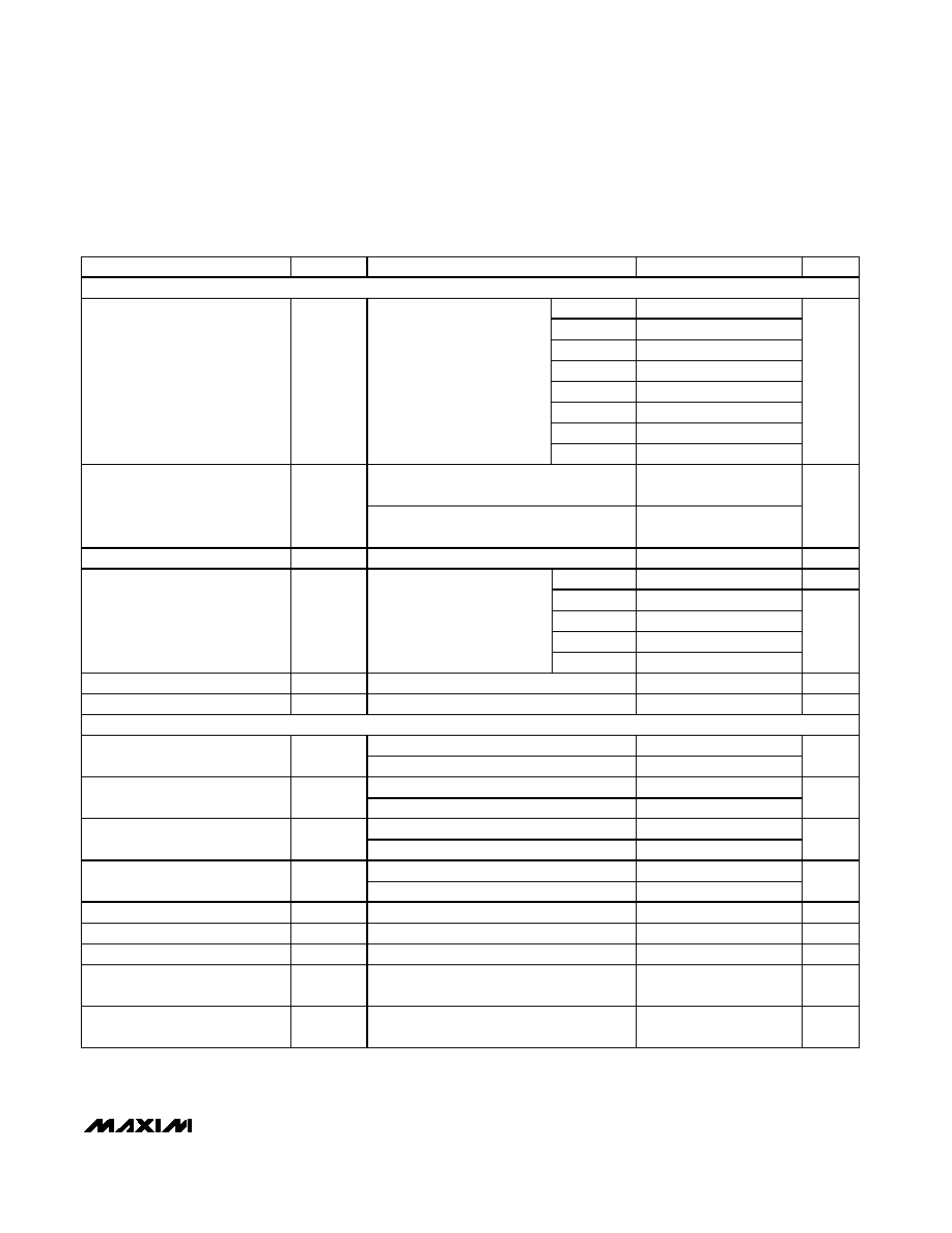
ABSOLUTE MAXIMUM RATINGS
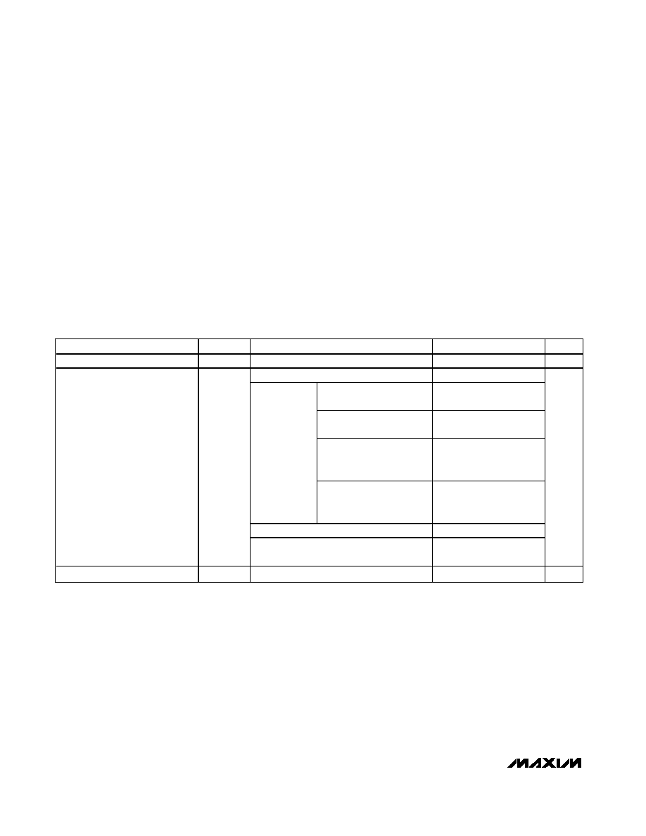
ELECTRICAL CHARACTERISTICS
(V
IN
= 14V, C
IN
= 1µF, C
OUT
= 10µF, T
A
= T
J
= -40∞C to +125∞C, unless otherwise noted. Typical values are at T
A
= T
J
= +25∞C.)
(Note 1)
Stresses beyond those listed under "Absolute Maximum Ratings" may cause permanent damage to the device. These are stress ratings only, and functional
operation of the device at these or any other conditions beyond those indicated in the operational sections of the specifications is not implied. Exposure to
absolute maximum rating conditions for extended periods may affect device reliability.
(All pins referenced to GND, unless otherwise noted.)
IN to GND ...............................................................-0.3V to +80V
ENABLE, ENABLE1, ENABLE2, PFI,
GATEP to GND ...........................................-0.3V to (IN + 0.3V)
GATEP to IN ...........................................................-12V to +0.3V
OUT, OUT1, OUT2, PFO, RESET (open-drain versions),
CSRT, CSWT .......................................................-0.3V to +12V
HOLD, RESET (push-pull versions), WDI, WDS0, WDS1,
WD-DIS, SET, SET1......................-0.3V to (OUT/OUT1 + 0.3V)
OUT, OUT1, OUT2 Short Circuit
to GND....................................................................Continuous
Maximum Current (all pins except IN and OUT_)...............50mA
Continuous Power Dissipation (T
A
= +70∞C)
20-Pin TQFN (derate 33.3mW/∞C above +70∞C) .....2666.7mW
Operating Temperature Range (T
A
) ..................-40∞C to +125∞C
Junction Temperature (T
J
) .................................................150∞C
Storage Temperature Range .............................-65∞C to +150∞C
Lead Temperature (soldering, 10s) .................................+300∞C
PARAMETER
SYMBOL
CONDITIONS
MIN
TYP
MAX
UNITS
Supply Voltage Range
V
IN
5
72
V
Regulators on (I
LOAD
= 0mA), V
IN
= 8V
68
85
V
IN
= 8V, I
LOAD
= 300mA
(MAX6795/MAX6796)
130
220
V
IN
= 14V, I
LOAD
= 100mA
(MAX6795/MAX6796)
100
160
V
IN
= 8V, I
LOAD1
= I
LOAD2
= 150mA
(MAX6791≠MAX6794)
130
220
Regulators on,
OUT/OUT1 =
OUT2 = 5V
V
IN
= 14V, I
LOAD1
=
I
LOAD2
= 50mA
(MAX6791≠MAX6794)
100
160
Regulators on (I
LOAD
= 0mA), V
IN
= 42V
74
95
Supply Current
I
IN
Regulators on (I
LOAD
= 20mA, total)
OUT1/OUT2/OUT = 5V, V
IN
= 42V
100
170
µA
Shutdown Supply Current
I
SHDN
Regulators off, V
IN
= 14V
27
45
µA
MAX6791≠MAX6796
High-Voltage, Micropower, Single/Dual Linear
Regulators with Supervisory Functions
_______________________________________________________________________________________
3
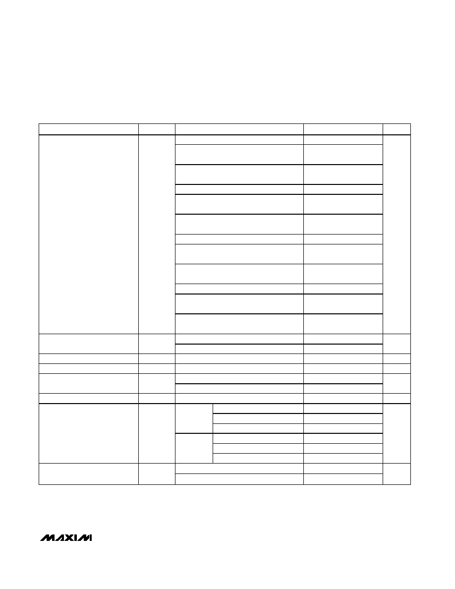
ELECTRICAL CHARACTERISTICS (continued)
(V
IN
= 14V, C
IN
= 1µF, C
OUT
= 10µF, T
A
= T
J
= -40∞C to +125∞C, unless otherwise noted. Typical values are at T
A
= T
J
= +25∞C.)
(Note 1)
PARAMETER
SYMBOL
CONDITIONS
MIN
TYP
MAX
UNITS
L/M, I
LOAD
= I
LOAD1
= 1mA
4.858
4.974
5.090
L/M, I
LOAD
= 150mA (MAX6791≠MAX6794),
V
IN
= 8V
4.811
4.945
5.078
L/M, I
LOAD
= 300mA (MAX6795/MAX6796),
V
IN
= 8V
4.850
5
5.150
T/S, I
LOAD
= I
LOAD1
= 1mA
3.206
3.282
3.360
T/S, I
LOAD
= 150mA (MAX6791≠MAX6794),
V
IN
= 6V
3.175
3.263
3.351
T/S, I
LOAD
= 300mA (MAX6795/MAX6796),
V
IN
= 6V
3.201
3.3
3.399
Z/Y, I
LOAD
= I
LOAD1
= 1mA
2.429
2.487
2.546
Z/Y, I
LOAD
= 150mA (MAX6791≠MAX6794),
V
IN
= 5.5V
2.405
2.472
2.539
Z/Y, I
LOAD
= 300mA (MAX6795/MAX6796),
V
IN
= 5.5V
2.425
2.5
2.575
W/V, I
LOAD
= I
LOAD1
= 1mA
1.748
1.791
1.832
W/V, I
LOAD
= 150mA (MAX6791≠MAX6794),
V
IN
= 5V
1.731
1.780
1.828
Output Voltage
V
OUT
/
V
OUT1
W/V, I
LOAD
= 300mA (MAX6795/MAX6796),
V
IN
= 5V
1.746
1.8
1.854
V
I
LOAD2
= 1mA
4.858
4.974
5.090
Output Voltage
(MAX6791≠MAX6794)
V
OUT2
I
LOAD2
= 150mA
4.811
4.945
5.079
V
SET/SET1 Threshold Voltage
V
SET
I
LOAD
= I
LOAD1
= 1mA, OUT/OUT1 = 5V
1.207
1.2315
1.256
V
Adjustable Output Voltage
V
OUT
1.8
11.0
V
SET/SET1 rising
124
Dual-ModeTM SET Threshold
SET/SET1 falling
62
mV
SET/SET1 Input Current
SET/SET1 = 1V, V
IN
= 11V
-100
+100
nA
L/M, I
LOAD
= 20mA (Note 2)
84
130
L/M, I
LOAD
= 300mA (Note 2)
1200
1800
(MAX6795/
MAX6796)
T/S, I
LOAD
= 300mA (Note 3)
1700
2400
L/M, I
LOAD
= 150mA (Note 2)
1000
1800
L/M, I
LOAD
= 10mA (Note 2)
84
130
Dropout Voltage
V
DO
(MAX6791≠
MAX6794)
T/S, I
LOAD
= 150mA (Note 3)
1700
2400
mV
M AX6795/M AX6796, i nfer red fr om d r opout test
300
Guaranteed Output Current
(Note 4)
MAX6791≠MAX 6794, inferr ed from d rop out test
150
mA
Dual Mode is a trademark of Maxim Integrated Products, Inc.
MAX6791≠MAX6796
High-Voltage, Micropower, Single/Dual Linear
Regulators with Supervisory Functions
4
_______________________________________________________________________________________
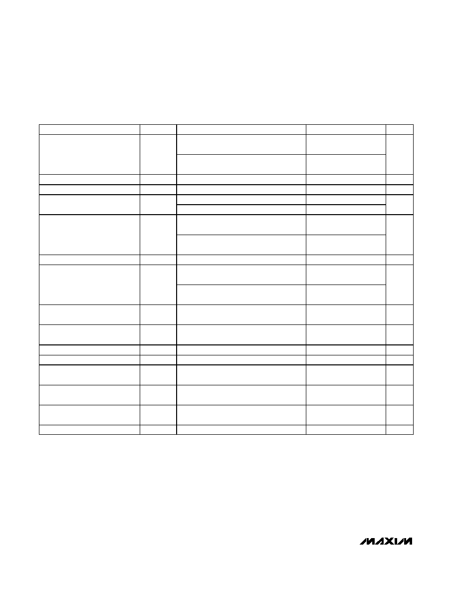
ELECTRICAL CHARACTERISTICS (continued)
(V
IN
= 14V, C
IN
= 1µF, C
OUT
= 10µF, T
A
= T
J
= -40∞C to +125∞C, unless otherwise noted. Typical values are at T
A
= T
J
= +25∞C.)
(Note 1)
PARAMETER
SYMBOL
CONDITIONS
MIN
TYP
MAX
UNITS
MAX6795/MAX6796, output shorted,
V
IN
= 6V
400
480
Short-Circuit Output Current Limit
(Note 4)
MAX6791≠MAX6794, output shorted,
V
IN
= 6V
200
240
mA
Thermal-Shutdown Temperature
+165
∞C
Thermal-Shutdown Hysteresis
20
∞C
8V
V
IN
72V, I
LOAD
= 1mA
1
Line Regulation
8V
V
IN
72V, I
LOAD
= 10mA
1
% of
V
OUT
I
OUT
= 1mA to 300mA
(MAX6795/MAX6796)
2
Load Regulation (Note 5)
I
OUT
= 1mA to 150mA
(MAX6791≠MAX6794)
1.5
%
Power-Supply Rejection Ratio
PSRR
I
LOAD
= 10mA, f = 100Hz, V
IN
= 500mV
P-P
69
dB
I
LOAD
= 300mA, V
OUT
= 5V,
OUT = 90% of its nominal value
180
Startup Response Time
t
START
I
LOAD
= 150mA, V
OUT
= 5V,
OUT1/OUT2 = 90% of its nominal value
360
µs
Output Overvoltage Protection
Threshold
OV
TH
I
SINK
= 1mA from OUT/OUT1/OUT2
1.05 x
V
OUT
1.1 x
V
OUT
V
Output Overvoltage Protection
Sink Current
V
OUT
= V
OUT
(nominal) x 1.15
5
10
mA
IN to GATEP Clamp Voltage
I
GATEP
= -100µA, V
IN
= 20V
13.8
16.3
18.8
V
IN to GATEP Drive Voltage
I
GATEP
= 0, V
IN
= 20V
8
10
12
V
ENABLE/ENABLE1/ENABLE2/
HOLD Input-Voltage Low
V
IL
0.4
V
ENABLE/ENABLE1/ENABLE2/
HOLD Input-Voltage High
V
IH
1.4
V
ENABLE/ENABLE1/ENABLE2
Input Pulldown Current
Enable is internally pulled down to GND
0.5
µA
HOLD Input Pullup Current
HOLD is internally pulled to OUT/OUT1
2
µA
MAX6791≠MAX6796
High-Voltage, Micropower, Single/Dual Linear
Regulators with Supervisory Functions
_______________________________________________________________________________________
5
ELECTRICAL CHARACTERISTICS (continued)
(V
IN
= 14V, C
IN
= 1µF, C
OUT
= 10µF, T
A
= T
J
= -40∞C to +125∞C, unless otherwise noted. Typical values are at T
A
= T
J
= +25∞C.)
(Note 1)
PARAMETER
SYMBOL
CONDITIONS
MIN
TYP
MAX
UNITS
RESET OUTPUT
L
4.500
4.625
4.750
M
4.250
4.375
4.500
T
2.970
3.053
3.135
S
2.805
2.888
2.970
Z
2.250
2.313
2.375
Y
2.125
2.188
2.250
W
1.620
1.665
1.710
Reset Threshold (Preset Output
Voltage)
SET/SET1 = GND
V
1.530
1.575
1.620
V
L/T/Z/W
0.90 x
V
OUT
0.925 x
V
OUT
0.95 x
V
OUT
Reset Threshold (Adjustable
Output Voltage)
M/S/Y/V
0.85 x
V
OUT
0.875 x
V
OUT
0.90 x
V
OUT
V
OUT to Reset Delay
V
OUT1
/V
OUT
falling
35
µs
D0
35
µs
D1
2.187
3.125
4.063
D2
8.75
12.5
16.25
D3
35
50
65
Reset Timeout Period
(CSRT = OUT/OUT1)
t
RP
V
OUT1
/V
OUT
rising
D4
140
200
260
ms
CSRT Ramp Current
800
1000
1250
nA
CSRT Ramp Threshold
1.185
1.218
1.255
V
WATCHDOG INPUT
CSWT = OUT/OUT1 (fixed)
280.0
400.0
520.0
Normal Watchdog Timeout Period
t
WD2
CSWT = 1500pF (adjustable)
170
236.2
290
ms
CSWT = OUT/OUT1 (fixed)
37.5
50.0
62.5
Fast Watchdog Timeout Period
SET Ratio = 8
t
WD1
CSWT = 1500pF (adjustable)
21.95
29.52
36.90
ms
CSWT = OUT/OUT1 (fixed)
18.75
25.0
31.25
Fast Watchdog Timeout Period
SET Ratio = 16
t
WD1
CSWT = 1500pF (adjustable)
10.80
14.76
18.45
ms
CSWT = OUT/OUT1 (fixed)
4.68
6.25
7.81
Fast Watchdog Timeout Period
SET Ratio = 64
t
WD1
CSWT = 1500pF (adjustable)
2.52
3.69
4.62
ms
Fast Watchdog Minimum Period
t
WD0
2000
ns
CSWT Ramp Current
Adjustable timeout
800
1000
1250
nA
CSWT Ramp Threshold
Adjustable timeout
1.185
1.218
1.255
V
Undercurrent Threshold for
Watchdog Enable
7.0
10
13.8
mA
Undercurrent Threshold for
Watchdog Disable
3
5
7
mA