General Description
Critical loads often employ parallel-connected power
supplies with redundancy to enhance system reliability.
The MAX8555/MAX8555A are highly integrated, inex-
pensive MOSFET controllers that provide isolation and
redundant power capability in high-reliability systems.
The MAX8555/MAX8555A are used in 0.5V to 3.3V sys-
tems, and have an internal charge pump to drive the
gates of the N-channel pass elements to (V
CS+
+ 5V).
During startup, the MAX8555/MAX8555A monitor the
voltage drop across the external MOSFETs. Once V
CS+
approaches or exceeds the bus voltage (V
CS-
), the
MOSFETs are turned on. The MAX8555/MAX8555A fea-
ture a dual-purpose TIMER input. A single external
resistor from TIMER to ground sets the turn-on speed of
the external MOSFETs. Optionally, the TIMER input can
be used as a logic enable input. Once the external
MOSFET is turned on, these controllers monitor the
load, protecting the bus against overvoltage, undervolt-
age, and reverse-current fault conditions. The
MAX8555 is available with a 40mV reverse-current
threshold, while the MAX8555A is available with a 20mV
reverse-current threshold.
Overvoltage and undervoltage fault thresholds are
adjustable and can be disabled. The current-limit trip
points are set by the external MOSFETs' R
DS(ON)
,
reducing component count. An open-drain, logic-low
fault output indicates if an overvoltage, undervoltage, or
reverse-current fault occurs. The MAX8555 and the
MAX8555A can shut down in response to a reverse-
current fault condition as quickly as 200ns.
Both devices come in space-saving 10-pin µMAX or
TDFN packages and are specified over the extended
-40∞C to +85∞C temperature range.
Applications
Point-of-Load Supplies
Power-Supply Modules
Servers
Telecom Power Supplies
Rectifiers
Redundant Power Supplies in High-Availability
Systems
Features
Simple, Integrated, and Inexpensive MOSFET
Controllers
ORing FET Drive for 0.5V to 3.3V
Eliminate ORing Diode Power Dissipation
Provide N+1 Redundant Supply Capability for
Highly Reliable Systems
Isolate Failed Short-Circuit Supply from
Output BUS
Respond to Reverse Short-Circuit Current
in 200ns
Adjustable Blank Time
Programmable Soft-Start
Logic Enable Input
Adjustable Overvoltage and Undervoltage
Trip Points
Fault-Indicator Output
Space-Saving Packages
MAX8555/MAX8555A
Low-Cost, High-Reliability, 0.5V to 3.3V ORing
MOSFET Controllers
________________________________________________________________
Maxim Integrated Products
1
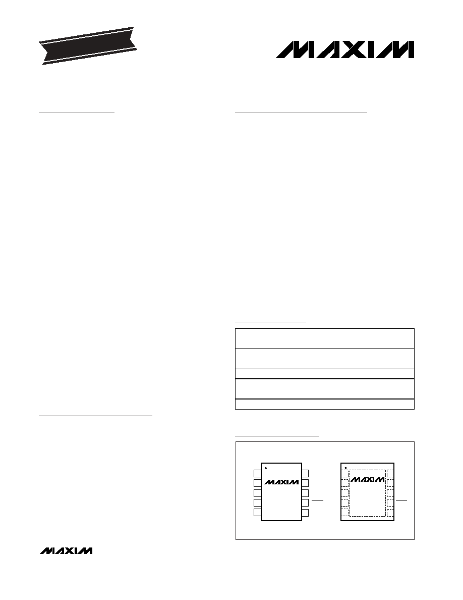
Ordering Information
13-3087; Rev 0; 1/04
For pricing, delivery, and ordering information, please contact Maxim/Dallas Direct! at
1-888-629-4642, or visit Maxim's website at www.maxim-ic.com.
EVALUATION KIT
AVAILABLE
PART
TEMP
RANGE
PIN-
PACKAGE
TOP
MARK
MAX8555
ETB
-40∞C to 85∞C
10 TDFN
3mm x 3mm*
ACC
MAX8555EUB
-40∞C to 85∞C
10 µMAX
8555EUB
MAX8555A
ETB
-40∞C to 85∞C
10 TDFN
3mm x 3mm*
ADD
MAX8555AEUB
-40∞C to 85∞C
10 µMAX
8555AEUB
1
2
3
4
5
10
9
8
7
6
CS+
CS-
OVP
V
DD
VL
GND
GATE
MAX8555/
MAX8555A
µ
MAX
TOP VIEW
TIMER
UVP
FAULT
1
2
3
4
5
10
9
8
7
6
CS+
CS-
OVP
V
DD
VL
GND
GATE
MAX8555/
MAX8555A
TDFN
TIMER
UVP
FAULT
Pin Configurations
*Exposed paddle
Typical Operating Circuit appears at end of data sheet.
MAX8555/MAX8555A
Low-Cost, High-Reliability, 0.5V to 3.3V ORing
MOSFET Controllers
2
_______________________________________________________________________________________
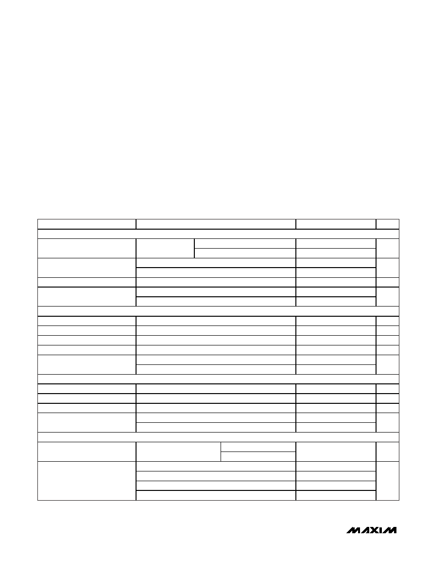
ABSOLUTE MAXIMUM RATINGS
ELECTRICAL CHARACTERISTICS
(V
DD
= 12V, V
CS-
= 1.4V, V
CS+
= 1.5V, R
TIMER
= 25k, V
UVP
= 1V, V
OVP
= 0.25V, R
FAULT
= 50k, C
VDD
= C
GATE
= C
VL
= 0.01µF,
T
A
= 0∞C to +85∞C, unless otherwise noted.)
Stresses beyond those listed under "Absolute Maximum Ratings" may cause permanent damage to the device. These are stress ratings only, and functional
operation of the device at these or any other conditions beyond those indicated in the operational sections of the specifications is not implied. Exposure to
absolute maximum rating conditions for extended periods may affect device reliability.
GATE to GND .........................................................-0.3V to +12V
FAULT, VL to GND ...................................................-0.3V to +6V
OVP, UVP, TIMER, CS+, CS- to GND .......-0.3V to +(V
VL
+ 0.3V)
V
DD
to GND..................................................(V
VL
- 0.3V) to +18V
Continuous Power Dissipation (T
A
= +70∞C)
10-Pin µMAX (derate 5.6mW/∞C above +70∞C) ...........444mW
10-Pin TDFN (derate 24.4mW/∞C above +70∞C) .......1951mW
Operating Temperature Range ...........................-40∞C to +85∞C
Junction Temperature ......................................................+150∞C
Storage Temperature Range .............................-65∞C to +150∞C
Lead Temperature (soldering, 10s) .................................+300∞C
PARAMETER
CONDITIONS
MIN
TYP
MAX
UNITS
V
DD
SUPPLY
VL unconnected
8.00
13.25
V
DD
Input Voltage
V
TIMER
= 2.5V
VL = V
DD
3.0
5.5
V
VL unconnected, V
TIMER
= 2.5V, V
DD
= 13.25V
2.0
3.3
V
DD
Supply Current
V
DD
= V
VL
= 5V, V
TIMER
= 2.5V
0.04
0.2
mA
V
DD
Shutdown Current
V
TIMER
= 0V, V
DD
= 13.25V
3.0
mA
Rising threshold
14.0
14.4
15.0
V
DD
Overvoltage Internal
Threshold
Falling threshold
13.3
13.8
14.5
V
VL SUPPLY
VL Input Voltage
V
DD
= V
VL
3.0
5.5
V
VL Supply Current
V
DD
= V
VL
= 5V, V
TIMER
= 2.5V
1.8
3.0
mA
VL Current in Shutdown Mode
TIMER = GND, V
DD
= V
VL
= 5V
1.6
3.0
mA
VL Output Voltage
V
DD
= 8V to 13.25V, I
VL
= 0A
3.80
4.1
4.45
V
VL = V
DD
, rising threshold
2.78
2.82
2.90
VL Undervoltage Lockout
VL = V
DD
, falling threshold
2.68
2.75
2.82
V
CS INPUTS
CS+, CS- Input Current
V
TIMER
= 2.5V, V
CS
= 3.0V
5.2
µA
Offset Input Current (CS+, CS-)
V
CS
= 3.0V, Figure 4
-250
+250
nA
CS+/CS- Input Range
(Note 1)
0.5
V
VL
- 0.5
V
V
CS+
= +3V, V
CS-
= 0V, I
CS-
-0.5
CS Isolation
V
CS-
= +3V, V
CS+
= 0V, I
CS+
-0.5
µA
CHARGE-PUMP VOLTAGE
V
DD
= 8V to 13.25V
GATE Voltage, V
GATE
Measured from GATE to CS+
V
DD
= V
VL
= 5V
5.0
5.25
5.5
V
R
TIMER
= 20k
187
R
TIMER
= 125k
450
R
TIMER
= open
500
Charge-Pump Switching
Frequency
V
TIMER
= 1.5V
550
kHz
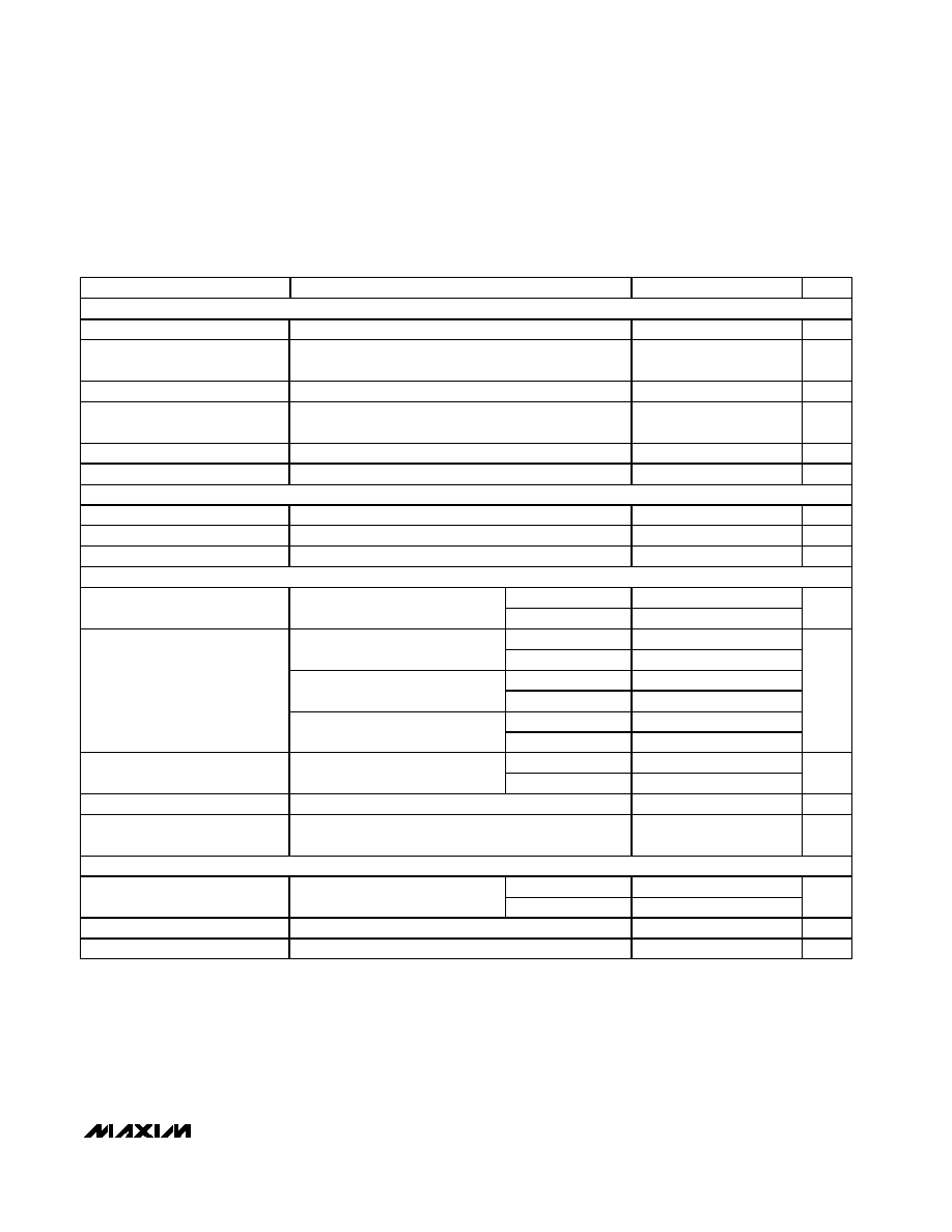
MAX8555/MAX8555A
Low-Cost, High-Reliability, 0.5V to 3.3V ORing
MOSFET Controllers
_______________________________________________________________________________________
3
ELECTRICAL CHARACTERISTICS (continued)
(V
DD
= 12V, V
CS-
= 1.4V, V
CS+
= 1.5V, R
TIMER
= 25k, V
UVP
= 1V, V
OVP
= 0.25V, R
FAULT
= 50k, C
VDD
= C
GATE
= C
VL
= 0.01µF,
T
A
= 0∞C to +85∞C, unless otherwise noted.)
PARAMETER
CONDITIONS
MIN
TYP
MAX
UNITS
TIMER
TIMER Voltage
1.22
1.25
1.28
V
TIMER Maximum Source Current
V
TIMER
= 1.0V
85
100
115
µA
TIMER High Input Current
V
TIMER
= 1.5V
10
15
µA
TIMER Maximum Frequency
Select Voltage Input Range
(Note 1)
1.5
V
VL
V
TIMER Logic High, V
IH
Charge pump enabled
1.0
V
TIMER Logic Low, V
IL
Charge pump disabled
0.5
V
FAULT
Fault Output Low Voltage
I
FAULT
= 10mA
0.2
V
Fault Sink Current
V
FAULT
= 0.4V
15
mA
Fault Leakage Current
V
FAULT
= 5.5V, T
A
= +25∞C
1
µA
GATE
MAX8555
80
100
120
Gate-On Threshold
Measured from CS- to CS+
MAX8555A
35
50
65
mV
R
TIMER
= open
17
25
33
V
GATE
= V
CS+
= 2.5V
R
TIMER
= 25k
8
12
16
R
TIMER
= open
15
V
GATE
= V
CS+
= 2.5V,
V
DD
= V
VL
= 3V
R
TIMER
= 25k
7.5
R
TIMER
= open
30
Gate-Drive Current
V
GATE
= V
CS+
= 2.5V,
V
DD
= V
VL
= 5V
R
TIMER
= 25k
15
µA
V
TIMER
falling
100
200
Gate Shutdown Delay
(Note 2)
I
REV
fault
60
150
ns
Gate Discharge Current
V
GATE
= V
CS+
= +5V
1000
mA
GATE Fall Time
Gate voltage fall from FAULT to V
GATE
= V
CS+
,
R1 = 2
, Figure 3 or Figure 4
0.2
µs
CURRENT SENSE
MAX8555
34
40
46
Reverse-Current Threshold
Measured from CS- to CS+
MAX8555A
16
20
24
mV
Startup I
REV
Blank Time
TIMER = unconnected
4.1
ms
Forward-Current Threshold
Measured from CS+ to CS-
6
10
14
mV
MAX8555/MAX8555A
Low-Cost, High-Reliability, 0.5V to 3.3V ORing
MOSFET Controllers
4
_______________________________________________________________________________________
ELECTRICAL CHARACTERISTICS (continued)
(V
DD
= 12V, V
CS-
= 1.4V, V
CS+
= 1.5V, R
TIMER
= 25k, V
UVP
= 1V, V
OVP
= 0.25V, R
FAULT
= 50k, C
VDD
= C
GATE
= C
VL
= 0.01µF,
T
A
= 0∞C to +85∞C, unless otherwise noted.)
PARAMETER
CONDITIONS
MIN
TYP
MAX
UNITS
OVERVOLTAGE PROTECTION
OVP rising
0.49
0.5
0.51
OVP Fault Threshold, V
OVP
OVP falling
0.4
V
T
A
= +25∞C
0.1
OVP
Bias Current
T
A
= +85∞C
0.021
µA
UNDERVOLTAGE PROTECTION
UVP rising
0.488
0.5
0.512
UVP Fault Threshold, V
UVP
UVP falling
0.4
V
T
A
= +25∞C
0.1
UVP
Bias Current
T
A
= +85∞C
0.003
µA
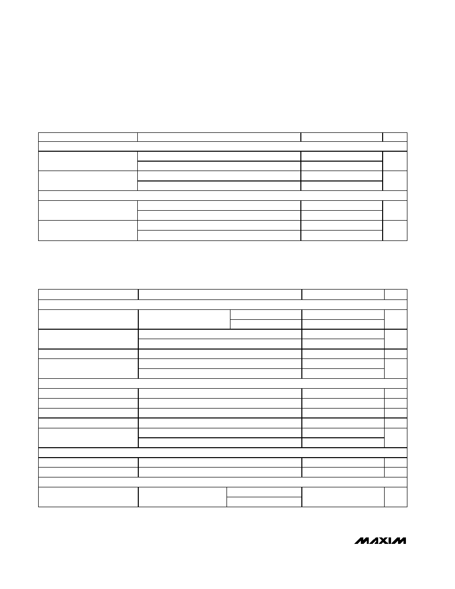
ELECTRICAL CHARACTERISTICS
(V
DD
= 12V, V
CS-
= 1.4V, V
CS+
= 1.5V, R
TIMER
= 25k, V
UVP
= 1V, V
OVP
= 0.25V, R
FAULT
= 50k, C
VDD
= C
GATE
= C
VL
= 0.01µF,
T
A
= -40∞C to +85∞C, unless otherwise noted.) (Note 3)
PARAMETER
CONDITIONS
MIN
TYP
MAX
UNITS
V
DD
SUPPLY
VL unconnected
8.00
13.25
V
DD
Input Voltage
V
TIMER
= 2.5V
VL = V
DD
3.0
5.5
V
VL unconnected, V
TIMER
= 2.5V, V
DD
= 13.25V
3.3
V
DD
Supply Current
V
DD
= V
VL
= 5V, V
TIMER
= 2.5V
0.2
mA
V
DD
Shutdown Current
V
TIMER
= 0V, V
DD
= 13.25V
3.0
mA
Rising threshold
14.0
15.0
V
DD
Overvoltage Internal
Threshold
Falling threshold
13.3
14.5
V
VL SUPPLY
VL Input Voltage
V
DD
= V
VL
3.0
5.5
V
VL Supply Current
V
DD
= V
VL
= 5V, V
TIMER
= 2.5V
3.0
mA
VL Current in Shutdown Mode
TIMER = GND, V
DD
= V
VL
= 5V
3.0
mA
VL Output Voltage
V
DD
= 8V to 13.25V, I
VL
= 0A
3.80
4.45
V
VL = V
DD
, rising threshold
2.78
2.90
VL Undervoltage Lockout
VL = V
DD
, falling threshold
2.68
2.82
V
CS INPUTS
Offset Input Current (CS+, CS-)
V
CS
= 3.0V, Figure 4
-250
+250
nA
CS+/CS- Input Range
(Note 1)
0.5
V
VL
- 0.5
V
CHARGE-PUMP VOLTAGE
V
DD
= 8V to 13.25V
GATE Voltage, V
GATE
Measured from GATE to CS+
V
DD
= V
VL
= 5V
5.0
5.5
V

MAX8555/MAX8555A
Low-Cost, High-Reliability, 0.5V to 3.3V ORing
MOSFET Controllers
_______________________________________________________________________________________
5
Note 1: Guaranteed by design. Not production tested.
Note 2: Gate shutdown delay is measured from reverse-current fault to the start of gate-voltage falling or from TIMER to the start of
gate-voltage falling.
Note 3: Specifications to -40∞C are guaranteed by design and not production tested.
ELECTRICAL CHARACTERISTICS (continued)
(V
DD
= 12V, V
CS-
= 1.4V, V
CS+
= 1.5V, R
TIMER
= 25k, V
UVP
= 1V, V
OVP
= 0.25V, R
FAULT
= 50k, C
VDD
= C
GATE
= C
VL
= 0.01µF,
T
A
= -40∞C to +85∞C, unless otherwise noted.) (Note 3)
PARAMETER
CONDITIONS
MIN
TYP
MAX
UNITS
TIMER
TIMER Voltage
1.22
1.28
V
TIMER Maximum Source Current
V
TIMER
= 1.0V
85
115
µA
TIMER High Input Current
V
TIMER
= 1.5V
15
µA
TIMER Maximum Frequency
Select Voltage Input Range
(Note 1)
1.5
V
VL
V
TIMER Logic High, V
IH
Charge pump enabled
1.1
V
TIMER Logic Low, V
IL
Charge pump disabled
0.5
V
FAULT
Fault Output Low Voltage
I
FAULT
= 10mA
0.2
V
Fault Sink Current
V
FAULT
= 0.4V
15
mA
GATE
MAX8555
80
120
Gate-On Threshold
Measured from CS- to CS+
MAX8555A
35
65
mV
R
TIMER
= open
17
33
Gate-Drive Current
V
GATE
= V
CS+
= 2.5V
R
TIMER
= 25k
8
16
µA
V
TIMER
falling
200
Gate Shutdown Delay
I
REV
fault
150
ns
CURRENT SENSE
MAX8555
34
46
Reverse-Current Threshold
Measured from CS- to CS+
MAX8555A
16
24
mV
Forward-Current Threshold
Measured from CS+ to CS-
6
14
mV
OVERVOLTAGE PROTECTION
OVP Fault Threshold, V
OVP
OVP rising
0.49
0.51
V
UNDERVOLTAGE PROTECTION
UVP Fault Threshold, V
UVP
UVP rising
0.488
0.512
V