
_______________General Description
The MAX8862 low-cost, low-dropout, dual linear voltage
regulator is ideal for battery-powered and portable
applications. The regulators have independent supply
inputs and provide 250mA and 100mA, respectively,
with a full-load dropout voltage of 160mV. Both regula-
tors use P-channel MOSFET pass transistors and main-
tain low quiescent current independent of load current.
In dropout, the MOSFET does not suffer from excessive
base currents, as do saturated PNP transistors.
The MAX8862 output voltage is preset to 4.95V (L),
3.175V (T), or 2.85V (R). This device employs Dual
ModeTM operation, allowing user-adjustable outputs
from +2V to +11V with external resistors. The input
supply-voltage range is 2.5V to 11.5V. Other features
include independent shutdown, power-good indicator,
short-circuit and reverse-battery protection, and ther-
mal shutdown.
The MAX8862's regulators are ideal power supplies for
the radio and the microcontroller (µC) used in digital,
cordless, and PCS phones. The main regulator is opti-
mized for superior transient and dynamic response,
while the secondary regulator exhibits low-output, wide-
band noise.
The MAX8862 comes in a 16-pin SO package with a
lead frame that uses multiple GND pins as a heat sink
for additional thermal dissipation.
________________________Applications
Cellular Phones
Cordless Phones
PCS Phones
PCMCIA Cards
Modems
Hand-Held Instruments
Electronic Planners
____________________________Features
o
Low Cost
o
Guaranteed 250mA and 100mA Output Currents,
with Current Limiting
o
Dual Mode Operation:
Fixed or Adjustable Output from +2V to +11V
o
+2.5V to +11.5V Input Range
o
160mV Dropout Voltage at 200mA Output Current
o
Low Supply Current--Even in Dropout
200µA Operating
<1µA Shutdown
o
Power-Good Indicator
o
Reverse-Battery Protection
o
Thermal Overload Protection
MAX8862
Low-Cost, Low-Dropout, Dual Linear Regulator
________________________________________________________________
Maxim Integrated Products
1
TOP VIEW
Narrow SO
16
15
14
13
12
11
10
9
1
2
3
4
5
6
7
8
MAX8862
IN1
SHDN1
PWROK1
GND
GND
OUT2
SET2
N.C.
N.C.
SET1
OUT1
GND
GND
REF2
SHDN2
IN2
__________________Pin Configuration
INPUT 1
2.5V TO 11.5V
INPUT 2
2.5V TO 11.5V
100k
OUTPUT 1
AT 250mA
OUTPUT 2
AT 100mA
3.3µF
1µF
2.2µF
0.1µF
1µF
GND SET1 SET2 GND
OUT1
OUT2
MAX8862
SHDN1
SHDN2
PWROK1
REF2
IN1
IN2
__________Typical Operating Circuit
19-1117; Rev 0; 8/96
SUFFIX
L
T
R
2.85
3.175
4.95
FIXED OUTPUT VOLTAGE (V)
______________Ordering Information
*Insert the desired suffix letter (from the table below) into the
blank to complete the part number.
For free samples & the latest literature: http://www.maxim-ic.com, or phone 1-800-998-8800
PART*
MAX8862_ESE
-40∞C to +85∞C
TEMP. RANGE
PIN-PACKAGE
16 Narrow SO
Dual Mode is a trademark of Maxim Integrated Products.
µ
VRMS
MAX8862
Low-Cost, Low-Dropout, Dual Linear Regulator
2
_______________________________________________________________________________________
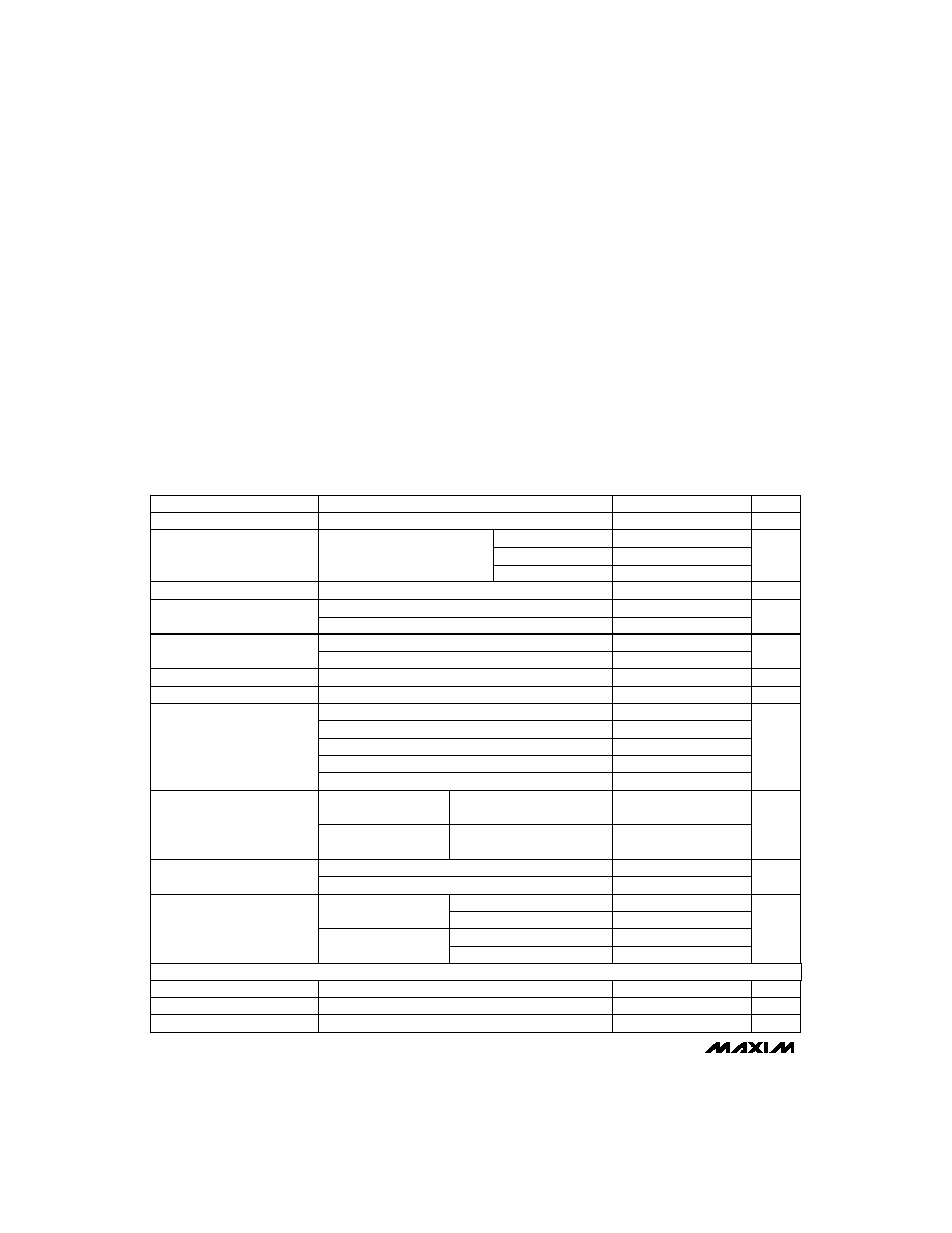
ABSOLUTE MAXIMUM RATINGS
ELECTRICAL CHARACTERISTICS (Notes 2, 3)
(V
IN_
= V
OUT_(TYP)
+ 1V,
T
A
= 0∞C to +85∞C
, unless otherwise noted. Typical values are at T
A
= +25∞C.)
Stresses beyond those listed under "Absolute Maximum Ratings" may cause permanent damage to the device. These are stress ratings only, and functional
operation of the device at these or any other conditions beyond those indicated in the operational sections of the specifications is not implied. Exposure to
absolute maximum rating conditions for extended periods may affect device reliability.
IN1, IN2 to GND (Note 1).....................................................±12V
SET1,
SHDN1, PWROK1 to GND.............. -0.3V to (V
IN1
+ 0.3V)
SET2,
SHDN2, REF2 to GND ....................... -0.3V, (V
IN2
+ 0.3V)
Output Short-Circuit Duration ............................................Infinite
Continuous Power Dissipation (T
A
= +70∞C)
16-Pin Narrow SO (derate 20mW/∞C above +70∞C) ............... 1W
Operating Temperature Range ...........................-40∞C to +85∞C
Junction Temperature .....................................................+150∞C
Storage Temperature Range .............................-65∞C to +150∞C
Lead Temperature (soldering, 10sec) ............................ +300∞C
I
OUT2
= 100mA, MAX8862R
V
IN1
= V
IN2
= 11.5V
I
OUT1
= 200mA, MAX8862R
I
OUT2
= 100mA, MAX8862L/T
I
OUT2
I
OUT1
0mA < I
OUT1
250mA,
0mA < I
OUT2
100mA
V
IN1
= 2.5V min, V
OUT1
= 2V
I
OUT1
= 200mA, MAX8862L/T
V
IN2
= 2.5V min, V
OUT2
= 2V
I
OUT1
= I
OUT2
= 1mA
CONDITIONS
%/mA
0.02
Load Regulation
0.015
%/V
0.02
0.08
Line Regulation
0.03
0.1
mV
180
400
Dropout Voltage (Note 4)
165
350
160
350
160
330
1.5
3.050
3.175
3.300
4.80
4.95
5.15
V
2.5
11.5
Input Voltage Range
µA
0.01
1
Shutdown Supply Current
µA
200
330
Quiescent Current
mA
250
Current Limit
580
V
2.75
2.85
2.95
V
2
11
Output Voltage Range
250
mA
100
Maximum Output Current
UNITS
MIN
TYP
MAX
PARAMETER
Note 1:
Connect
SHDN1 to IN1 and SHDN2 to IN2 through 20k
resistors to limit current flow in case a battery is reversed.
REF2 Output Voltage
C
REF2
= 0.1µF
1.230
1.250
1.270
V
REF2 Line Regulation
V
IN2
= 2.5V to 11.5V
1
mV
MAX8862L
MAX8862T
MAX8862R
V
IN1
= (V
OUT1 (TYP)
+ 1V)
to 11.5V
V
IN2
= (V
OUT2 (TYP)
+ 1V)
to 11.5V
REF2 Load Regulation
I
REF2
= 0µA to 10µA
6
mV
Output Voltage
I
OUT1
= I
OUT2
= 15mA
I
OUT1
= 0mA to 250mA, C
OUT1
= 3.3µF
I
OUT2
= 0mA to 100mA, C
OUT2
= 2.2µF
C
OUT2
= 2.2
µ
F
Z
OUT2
= 10mA
10Hz < f < 100kHz
10Hz < f < 1MHz
875
277
C
OUT2
= 100
µ
F
Z
OUT2
= 10mA
10Hz < f < 100kHz
10Hz < f < 1MHz
mV
RMS
667
OUT2 Voltage Noise
211
REFERENCE

MAX8862
Low-Cost, Low-Dropout, Dual Linear Regulator
_______________________________________________________________________________________
3
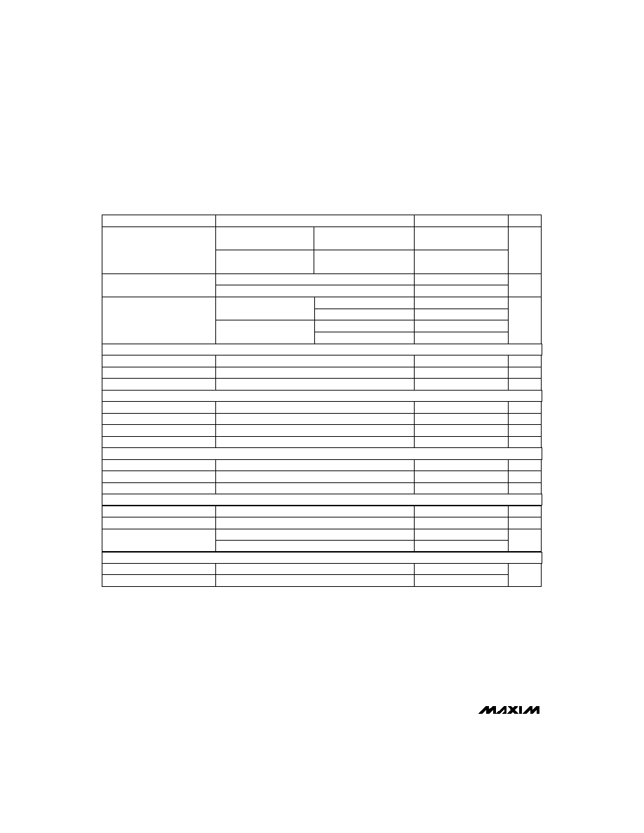
ELECTRICAL CHARACTERISTICS (Notes 2, 3)
(V
IN_
= V
OUT_(TYP)
+ 1V,
T
A
= 0∞C to +85∞C
, unless otherwise noted. Typical values are at T
A
= +25∞C.)
ELECTRICAL CHARACTERISTICS (Notes 2, 3)
(V
IN_
= V
OUT_(TYP)
+ 1V,
T
A
= -40∞C to +85∞C
, unless otherwise noted. Typical values are at T
A
= +25∞C.)
V
PWROK1
= 11.5V
Rising edge at SET1
SET_ = OUT_, I
OUT1
= I
OUT2
= 15mA
External feedback
V
SHDN_
= 11.5V
Active mode, V
IN_
= 11.5V
I
SINK
= 0.5mA
Internal feedback
Shutdown mode, V
IN_
= V
OUT_(TYP)
+ 1V to 11.5V
V
SET_
= 1.30V
CONDITIONS
∞C
20
Thermal Shutdown Hysteresis
160
Thermal Shutdown Temperature
mV
250
SET_ Threshold
40
µA
0.01
0.1
SET_ Input Bias Current
µA
0.01
1
PWROK1 Leakage Current
mV
15
PWROK1 Hysteresis
V
1.23
1.25
1.28
SET_ Reference Voltage
µA
0.01
1
SHDN_ Leakage Current
V
1.8
SHDN_ Logic High
mV
25
200
PWROK1 Low Voltage
V
0.45
SHDN_ Logic Low
UNITS
MIN
TYP
MAX
PARAMETER
Falling edge at SET1
V
1.175
1.200
1.225
PWROK1 Trip Voltage
SHDN
PWROK1 OUTPUT
SET_ INPUT
THERMAL PROTECTION
I
OUT2
= 100mA, MAX8862R
V
IN1
= V
IN2
= 11.5V
I
OUT1
= 200mA, MAX8862R
I
OUT2
= 100mA, MAX8862L/T
I
OUT2
I
OUT1
0mA < I
OUT1
250mA,
0mA < I
OUT2
100mA
V
IN1
= 2.5V min, V
OUT1
= 2V
I
OUT1
= 200mA, MAX8862L/T
V
IN2
= 2.5V min, V
OUT2
= 2V
I
OUT1
= I
OUT2
= 1mA
CONDITIONS
MAX8862L
MAX8862T
MAX8862R
mV
180
400
Dropout Voltage (Note 4)
165
350
160
350
160
330
1.5
3.050
3.175
3.300
4.80
4.95
5.15
V
2.5
11.5
Input Voltage Range
µA
0.01
1
Shutdown Supply Current
µA
200
330
Quiescent Current
mA
250
Current Limit
580
V
2.740
2.85
2.960
Output Voltage
V
2
11
Output Voltage Range
250
mA
100
Maximum Output Current
UNITS
MIN
TYP
MAX
PARAMETER
MAX8862
Low-Cost, Low-Dropout, Dual Linear Regulator
4
_______________________________________________________________________________________
ELECTRICAL CHARACTERISTICS (Notes 2, 3) (continued)
(V
IN_
= V
OUT_(TYP)
+ 1V,
T
A
= -40∞C to +85∞C
, unless otherwise noted. Typical values are at T
A
= +25∞C.)
REF2 Load Regulation
I
OUT1
= 0 to 250mA, C
OUT1
= 3.3µF
I
REF2
= 0µA to 10µA
6
mV
CONDITIONS
%/mA
0.02
Load Regulation
0.015
%/V
0.02
0.10
Line Regulation
V
IN1
= (V
OUT1 (TYP)
+ 1V)
to 11.5V
0.03
0.12
V
IN2
= (V
OUT2 (TYP)
+ 1V)
to 11.5V
UNITS
MIN
TYP
MAX
PARAMETER
-
277
-
REF2 Output Voltage
C
REF2
= 0.1µF
1.217
1.250
1.277
V
REF2 Line Regulation
V
IN2
= 2.5V to 11.5V
1
mV
PWROK1 Trip Voltage
Falling edge at SET1
1.165
1.200
1.235
V
PWROK1 Hysteresis
Rising edge at SET1
15
mV
PWROK1 Leakage Current
V
PWROK1
= 11.5V
0.01
1
µA
PWROK1 Low Voltage
I
SINK
= 0.5mA
25
200
mV
SHDN_ Logic Low
SHDN_ Logic High
Active mode, V
IN_
= 11.5V
2.0
V
SHDN_ Leakage Current
V
SHDN_
= 11.5V
0.02
1
µA
SET_ Reference Voltage
SET_ = OUT_, I
OUT1
= I
OUT2
= 15mA
1.220
1.250
1.290
V
SET_ Input Bias Current
V
SET_
= 1.30V
0.01
0.1
µA
Internal feedback
30
SET_ Threshold
External feedback
250
mV
Thermal Shutdown Temperature
160
Thermal Shutdown Hysteresis
10
∞C
Note 2:
Guaranteed by design for T
A
= -40∞C.
Note 3:
Guaranteed for a junction temperature (T
J
) equal to the operating temperature range. E-grade parts are guaranteed by
design to operate up to T
J
= +125∞C. For T
J
above +125∞C, specifications exceed the operating limits.
Note 4:
Dropout voltage is (V
IN
_ - V
OUT
_) when V
OUT
_ falls to 100mV below its nominal value at V
IN
_ = (V
OUT
_ + 1V). For example,
the MAX8862 is tested by measuring the V
OUT
_ at (V
IN_
= 5.95V for the MAX8862L, V
IN_
= 4.175V for the MAX8862T, and
V
IN_
= 3.85V for the MAX8862R) then V
IN_
is lowered until V
OUT_
falls 100mV below the measured value.
0.45
V
Shutdown mode, V
IN_
= V
OUT_(TYP)
+ 1V to 11.5V
I
OUT1
= I
OUT2
= 15mA
C = 2.2µF, Z
OUT2
= 10mA
-
875
-
C
OUT2
= 2.2µF, 10Hz < f < 1MHz, I
OUT2
= 10mA
10Hz < f < 100kHz
C = 100µF, Z
OUT2
= 10mA
-
667
-
10Hz < f < 100kHz
OUT2 Voltage Noise
-
211
-
µV
RMS
REFERENCE
PWROK1 OUTPUT
SHDN
SET_ INPUT
THERMAL PROTECTION
10Hz < f < 1MHz
10Hz < f < 1MHz
MAX8862
Low-Cost, Low-Dropout, Dual Linear Regulator
_______________________________________________________________________________________
5
120
80
0.001
1
1000
QUIESCENT CURRENT
vs. LOAD CURRENT
90
MAX8862 TOC03
LOAD CURRENT (mA)
QUIESCENT CURRENT (µA)
100
110
0.01
0.1
10
100
I
Q2
I
Q1
0
-40
SHUTDOWN CURRENT
vs. TEMPERATURE
TEMPERATURE (∞C)
SHUTDOWN CURRENT (nA)
20
40
60
80
100
-20
0
20
40
60
80
100
120
MAX8862 TOC01
V
IN1
= V
IN2
= 7V
V
IN1
= V
IN2
= 12V
100
-40
QUIESCENT CURRENT
vs. TEMPERATURE
TEMPERATURE (∞C)
QUIESCENT CURRENT (µA)
140
160
0
40
80
200
260
MAX8862 TOC02
V
IN1
= V
IN2
= 12V
V
IN1
= V
IN2
= 7V
-20
20
60
100
120
180
220
240
V
OUT1
/V
OUT2
4
0
4
7
MAX8862T
OUTPUT VOLTAGE & QUIESCENT CURRENT
vs. SUPPLY VOLTAGE
3
SUPPLY VOLTAGE (V)
OUTPUT VOLTAGE (V)
2
3
5
6
1
2
MAX8862TOC05
8
9
10 11
12
260
240
220
180
200
160
140
120
100
(I
Q1
+ I
Q2
)
QUIESCENT CURRENT (µA)
600
0
0
80
200
320
DROPOUT VOLTAGE
vs. LOAD CURRENT
150
450
MAX8862TOC07
LOAD CURRENT (mA)
DROPOUT VOLTAGE (mV)
120
280
300
525
375
225
75
40
240
160
OUT1
OUT2
3.27
3.20
0
60
OUTPUT VOLTAGE
vs. TEMPERATURE
3.25
TEMPERATURE (∞C)
OUTPUT VOLTAGE (V)
-40
-20
20
40
3.21
3.23
MAX8862TOC06
80
100
OUT1
OUT2
3.26
3.24
3.22
101
95
0.001
1
1000
OUTPUT VOLTAGE
vs. LOAD CURRENT
98
MAX8862TOC04
LOAD CURRENT (mA)
NORMALIZED OUTPUT VOLTAGE (%)
99
100
0.01
0.1
10
100
V
OUT1
V
OUT2
96
97
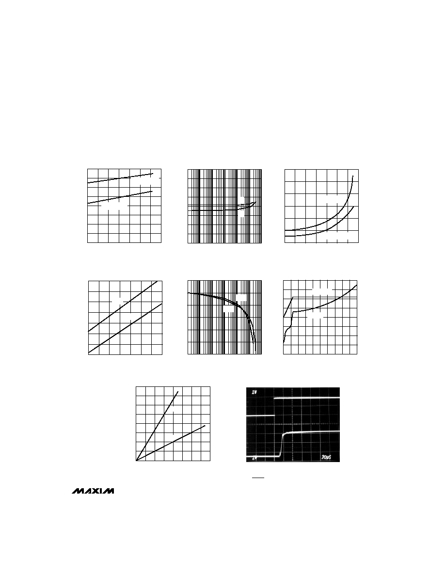
__________________________________________Typical Operating Characteristics
(V
IN1
= V
IN2
= 5.3V, C
IN1
= C
IN2
= 1µF, C
OUT1
= 3.3µF, C
OUT2
= 2.2µF,
SHDN1 = IN1, SHDN2 = IN2. T
A
= +25∞C, unless
otherwise noted.)
OVERSHOOT AND TIME
EXITING SHUTDOWN MODE
MAX8862TOC14
20µs/div
V
IN1
= 5.3V, I
OUT1
= 5mA
A = SHDN1, 0.8V TO 2.4V, 1V/div
B = OUT1, 1V/div
0V
0V
B
A
1V/div
1V/div