25 Amp Schottky
30 to 40 Volts
Features
Maxi mum Rati ngs
∑
Operating
Junction Temperature: -65
∞
C to +150
∞
C
∑
Storage Temperature: -65
∞
C to +150
∞
C
MCC
Part Number
Maximum
Recurrent
Peak Reverse
Voltage
Maximum
RMS Voltage
Maximum DC
Blocking
Voltage
Electrical Characteristics @ 25
∞
C Unless Otherwise Specified
Average Forward
Current
I
F(AV)
25 A T
A
=
70∞
C
Peak Forward Surge
Current
I
FSM
400A 8.3ms, half sine
Maximum
Instantaneous
Forward Voltage
V
F
I
FM
= 78.5
A;
T
C
=
70∞
C
Maximum DC
Reverse Current At
Rated DC Blocking
Voltage
I
R
20mA T
A
= 25
∞
C
M C C
∑
Metal of siliconrectifier, majonty carrier conducton
∑
Guard ring for transient protection
∑
Low power loss high efficiency
∑
High surge capacity, High current capability
*Pulse Test: Pulse Width 300
µ
sec, Duty Cycle
2%
1N6095
thru
1N6096
1N6096
40V 28V 40V
1N6095
30V 21V 30V
.86V
omponents
21201 Itasca Street Chatsworth
!"#
$
% !"#
250mA T
A
=
125
∞
C
M
N
B
C
J
P
F
G
D
E
H
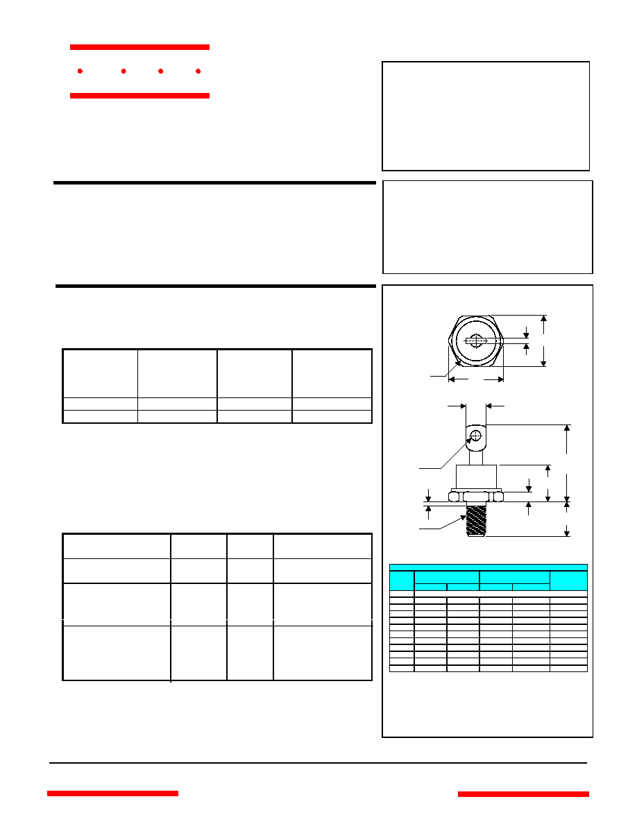
A
DO-
4
DIMENSIONS
INCH
ES
MM
DIM
MIN
MAX
MIN
MAX
NOTE
A
10-32 UNF3A Threads Standard Polarity
B .
424 .437 10.77 11.10
C ----- .
505 ----- 12.82
D
.600 .800 15.24 20.32
E
.422
.453
10.72
11.50
F .
075 .175 1.91 4.44
G ----- .4
05 ----- 10.29
H .
163 .189 4.15 4.80
J ----- .3
10 ----- 7.87
M ----- .
350 ----- 8.89
N
.020 .065 0.51 1.65
P .0
60 .100 1.53 2.54
www.
mccsemi
.com

Average Forward Rectified Current - Amperes versus
Ambient Temperature -
∞
C
Figure 2
Forward Derating Curve
0 150
30 50
70 100
0
5
10
15
Single Phase, Half Wave
60Hz Resistive or Inductive Load
Amps
∞
C
1
25
20
25
30
Instantaneous Forward Current - Amperes versus
Instantaneous Forward Voltage - Volts
Figure 1
Typical Forward Characteristics
40
60
200
100
Amps
0.
2 0.3 0.4 0.6 0.8 1.0
.1
.2
.4
.6
1
2
4
6
10
20
70
∞
C
Volts
1N6095 thru 1N6096
M C C
1
100
4
0
100
200
300
8
Figure 3
Peak Forward Surge Current
Peak Forward Surge Current - Amperes versus
Number Of Cycles At 60Hz - Cycles
Amps
Cycles
2 6 10 20 60 80
40
400
500
600
Instantaneous Reverse Leakage Current - MicroAmperes versus
Percent Of Rated Peak Reverse Voltage - Volts
Figure 4
Typical Reverse Characteristics
Volts
40
60
200
100
mAmps
20 80
40 50 60 70
.1
.2
.4
.6
1
2
4
6
10
20
T
A
=
25
∞
C
300
400
500
90
T
A
=
125
∞
C
www.
mccsemi
.com