CPT30035
THRU
CPT30090
300 Amp
Rectifier
30 to 90 Volts
Features
∑
Operating Temperature: -65
∞
C to +150
∞
C
∑
Storage Temperature: -65
∞
C to +150
∞
C
MCC
Part Number
Maximum
Recurrent
Peak Reverse
Voltage
Maximum
RMS Voltage
Maximum DC
Blocking
Voltage
CPT30035
35V 24.5V 35V
CPT30040
40V 28 V 30V
CPT30045 4
5V 31.5V 45V
CPT30050
50V 35 V 50V
CPT30060
60V 42 V 60V
CPT30080
80V 56 V 80V
CPT30090
90V 63 V 90V
Electrical Characteristics @ 25
∞
C Unless Otherwise Specified
Average Forward
Current
I
F(AV)
3
00 A T
L
=
136∞
C
Peak Forward Surge
Current
I
FSM
2000A 8.3ms, half sine
Maximum
Instantaneous
Forward Voltage
V
F
I
FM
=
150 A;
T
A
= 25
∞
C
Maximum DC
Reverse Current At
Rated DC Blocking
Voltage
I
R
4
mA
T
A
= 25
∞
C
Typical Junction
Capacitance
C
J
4600pF Measured at
1.0MHz, V
R
=4.0V
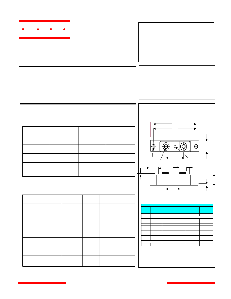
DIMENSIONS
INCH
ES
MM
DIM
MIN
MAX
MIN
MAX
NOTE
B 0
.700 0.800 17.78 20.32
A ---- 3.630 ----- 92.20
C
---- 0.630 ----- 16.00
N ------ ------ ------ ------ 1/4
F
0.490 0.510 12.45 12.95
E 0.120 0.130 3.05 3.30
G 1.375 BSC 34.92 BSC
H 0.010 ---- 0.25 ------
Q 0.275 0.290 6.99 7.37
www.
mccsemi
.com
Schottky Barrier
Maximum Ratings
∑
Metal of siliconrectifier, majonty carrier conducton
∑
Guard ring for transient protection
∑
Low power loss high efficiency
∑
High surge capacity, High current capability
*Pulse Test: Pulse Width 300
µ
sec, Duty Cycle 1%
3
0035-30050
3
0060
3
0080-30090
.70 V
.98 V
.82 V
R 3.150 BSC 80.01 BSC
U .600 ---- 15.24 -----
Did
Power Mod
( Twin Tower )
R
G
Q
A
W
B
N
F
U
H
E
C
V
V .312 .340 7.92 8.64
W .180 .195 4.57 4.95 Did
omponents
21201 Itasca Street Chatsworth
!"#
$
% !"#
M C C
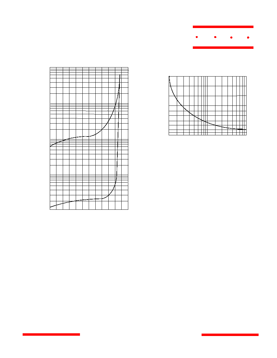
Junction Capacitance - pF versus
Reverse Voltage - Volts
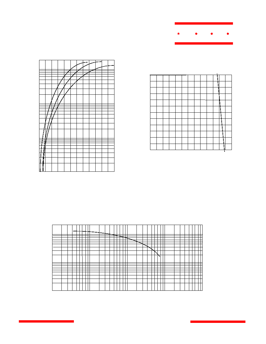
Instantaneous Forward Current - Amperes versus
Instantaneous Forward Voltage - Volts
Figure 1
Typical Forward Characteristics
40
60
200
100
Amps
0.
4 0.6 0 . 8 1.0 1.2 1.4
.1
.2
.4
.6
1
2
4
6
10
20
25
∞
C
Volts
Figure 3
Junction Capacitance
.1
.2
1
.4
2
10
20
40
4
100 200
10
20
60
100
200
3000
pF
Volts
2000
1000
40
400
1000
T
J
=25
∞
C
CPT30035 thru CPT30090
www.
mccsemi
.com
M C C
Average Forward Rectified Current - Amperes versus
Ambient Temperature -
∞
C
Figure 2
Forward Derating Curve
0 150
50 7
0 90 110
0
50
100
150
Single Phase, Half Wave
60Hz Resistive or Inductive Load
Amps
∞
C
1
30
200
250
300
30080-30090
30060
30035-30050
CPT30035 thru CPT30090
www.
mccsemi
.com
M C C
Instantaneous Reverse Leakage Current - MicroAmperes versus
Percent Of Rated Peak Reverse Voltage - Volts
Figure 4
Typical Reverse Characteristics
Volts
40
60
200
100
mAmps
10 100
20 40 60 80
.1
.2
.4
.6
1.0
2
.0
3.0
4.0
8.0
20
T
A
=
125
∞
C
400
600
1000
120
T
A
=25
∞
C
1
100
4
0
200
600
8
00
8
Figure
5
Peak Forward Surge Current
Peak Forward Surge Current - Amperes versus
Number Of Cycles At 60Hz - Cycles
Amps
Cycles
2
6
10 20
60 80
40
1000
15
00
2000