DL5817
THRU
DL5819
1 Amp Schottky
Barrier Rectifier
20 to 40 Volts
MELF
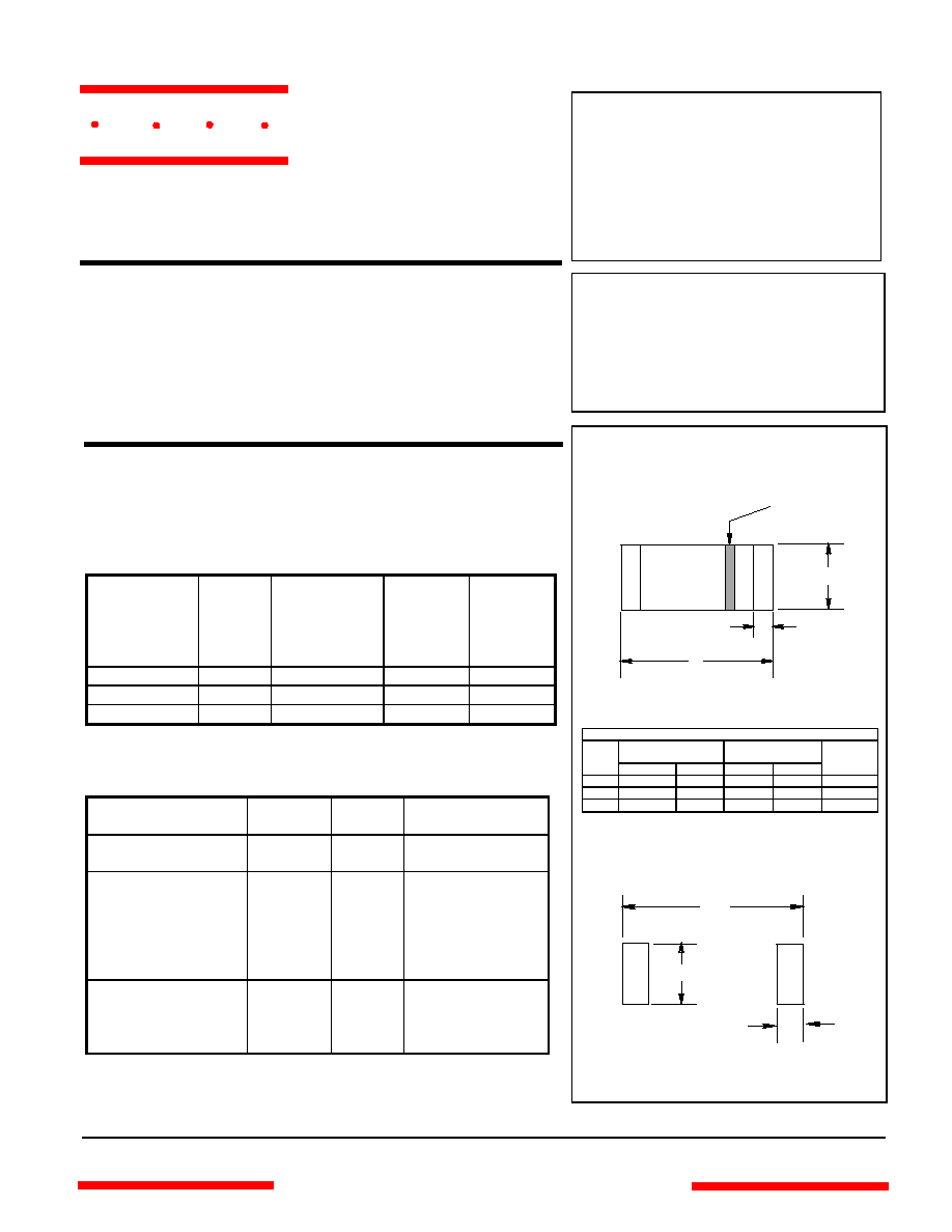
SUGGESTED SOLDER
PAD LAYOUT
Features
∑
Schottky Barrier Rectifier
∑
Guard Ring Protection
∑
Low Forward Voltage
∑
Low Power Loss For High Efficiency
∑
High Current Capability
∑
Surface Mount Applications
DIMENSIONS
INCHES
MM
DIM
MIN
MAX
MIN
MAX
NOTE
A
.190
.205
4.80
5.20
B
---
.022
---
.55
Nominal
C .095 .105 2.40 2.67
Maximum Ratings
∑
Operating Temperature: -55
∞
C to +125
∞
C
∑
Storage Temperature: -55
∞
C to +150
∞
C
∑
Maximum Thermal Resistance; 15
∞
C/W Junction To Lead
MCC
Catalog
Number
Device
Marking
Maximum
Recurrent
Peak
Reverse
Voltage
Maximum
RMS
Voltage
Maximum
DC
Blocking
Voltage
DL5817 --- 20V 14V 20V
DL5818 --- 30V 21V 30V
DL5819 --- 40V 28V 40V
Electrical Characteristics @ 25
∞
C Unless Otherwise Specified
Average Forward
Current
I
F(AV)
1.0A
T
A
= 90
∞
C
Peak Forward Surge
Current
I
FSM
25A
8.3ms, half sine
Maximum
Instantaneous
Forward Voltage
DL5817
DL5818
DL5819
V
F
.45V
.55V
.60V
I
FM
= 1.0A;
T
J
= 25
∞
C*
Maximum DC
Reverse Current At
Rated DC Blocking
Voltage
I
R
1.0mA
T
J
= 25
∞
C
*Pulse test: Pulse width 300
µ
sec, Duty cycle 2%
A
B
C
Cathode Mark
.220"
.035"
.115"
www.
mccsemi
.com
omponents
21201 Itasca Street Chatsworth
!"#
$
% !"#
M C C
Figure 1
Typical Forward Characteristics
Instantaneous Forward Current - Amperes
versus
Instantaneous Forward Voltage - Volts
0
.2
.4
.6
.8
1.0
1.2
1.4
.1
.2
.4
.6
.8
1.0
2.0
4.0
6.0
8.0
10
20
40
60
80
100
Volts
Amps
Figure 3
Typical Reverse Characteristics
0
5
10
15 20
25 30
35
40
45
50
.001
.01
.1
1
10
100
125
∞
C
75
∞
C
25
∞
C
Typical Reverse Current - mA
versus
Reverse Voltage - Volts
mA
Volts
25
∞
C
125
∞
C
Figure 2
Typical Junction Capacitance
Junction Capacitance - pF
versus
Reverse Voltage - Volts
Volts
pF
0.1
0.5
1.0
5.0
10
50
100
10
20
40
60
100
200
400
600
1000
M C C
www.
mccsemi
.com
DL5817

DL5818 thru DL5819
Instantaneous Forward Current - Amperes
versus
Instantaneous Forward Voltage - Volts
Figure 1
Typical Forward Characteristics
0
.2
.4
.6
.8
1.0
1.2
1.4
.1
.2
.4
.6
.8
1.0
2.0
4.0
6.0
8.0
10
20
40
60
80
100
25
∞
C
Volts
Amps
Figure 3
Typical Reverse Characteristics
0
4
8
12
16
20 24
28
32
36
40
.001
.01
.1
1
10
100
25
∞
C
Typical Reverse Current - mA
versus
Reverse Voltage - Volts
mA
Volts
125
∞
C
Figure 2
Typical Junction Capacitance
Junction Capacitance - pF
versus
Reverse Voltage - Volts
Volts
pF
0.
0.5
1.0
5.0
10
50
100
10
20
40
60
100
200
400
600
1000
75
∞
C
125
∞
C
5818
5819
M C C
www.
mccsemi
.com