
MMBD4148
350mW 100 Volt
Silicon Epitaxial Diode
SOT-23
Suggested Solder
Pad Layout
Features
∑
Low Current Leakage
∑
Low Cost
∑
Small Outline Surface Mount Package
DIMENSIONS
INCHES
MM
DIM
MIN
MAX
MIN
MAX
NOTE
A
.110
.120
2.80
3.04
B
.083
.098
2.10
2.64
C
.047
.055
1.20
1.40
D
.035
.041
.89
1.03
E
.070
.081
1.78
2.05
F
.018
.024
.45
.60
G
.0005
.0039
.013
.100
H
.035
.044
.89
1.12
J
.003
.007
.085
.180
K
.015
.020
.37
.51
Maximum Ratings
∑
Operating Temperature: -55
∞
C to +150
∞
C
∑
Storage Temperature: -55
∞
C to +150
∞
C
∑
Maximum Thermal Resistance; 357K/W Junction To Ambient
Electrical Characteristics @ 25
∞
C Unless Otherwise Specified
Reverse Voltage
V
R
75V
Peak Reverse
Voltage
V
RM
100V
Average Rectified
Current
I
O
150mA
Resistive Load
f > 50Hz
Power Dissipation
P
TOT
350mW
Junction
Temperature
T
J
150
∞
C
Peak Forward Surge
Current
I
FSM
1A t=1s,
Non-Repetitive
Maximum
Instantaneous
Forward Voltage
V
F
.855V I
FM
= 10mA;
T
J
= 25
∞
C*
Maximum DC
Reverse Current At
Rated DC Blocking
Voltage
I
R
25nA
T
J
= 25
∞
C
V
R
= 20 V
Typical Junction
Capacitance
C
J
2pF Measured at
1.0MHz, V
R
=0V
Reverse Recovery
Time
T
rr
4nS
I
F
=10mA
V
R
= 6V
R
L
=100
*Pulse test: Pulse width 300
µ
sec, Duty cycle 2%
A
B
C
D
E
F
G
H
J
.079
2.000
inches
mm
.031
.800
.035
.900
.037
.950
.037
.950
KA2
C
A
Pin Configuration
Top View
www.
mccsemi
.com
omponents
21201 Itasca Street Chatsworth
!"#
$
% !"#
M C C

MMBD4148
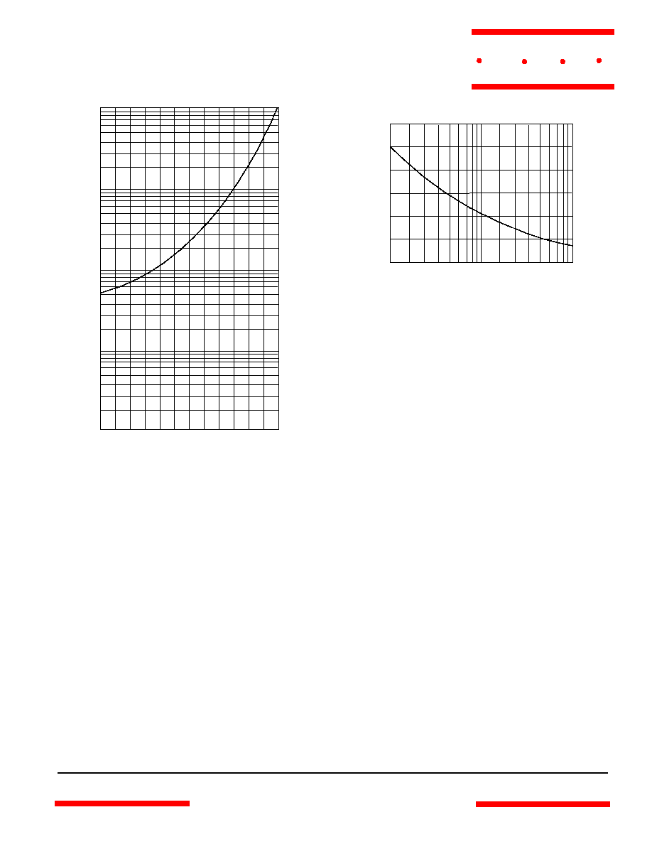
Admissable Power Dissipation - MilliWatts
versus
Ambient Temperature -
∞
C
Figure 2
Forward Derating Curve
0
175
50
75
100
125
0
70
140
210
Single Phase, Half Wave
60Hz Resistive or Inductive Load
MilliWatts
∞
C
150
280
350
420
Junction Capacitance - pF
versus
Reverse Voltage - Volts
Instantaneous Forward Current - Amperes
versus
Instantaneous Forward Voltage - Volts
Figure 1
Typical Forward Characteristics
4
6
20
10
MilliAmps
.4
.6
.8
1.0
1.2
1.4
.01
.02
.04
.06
.1
.2
.4
.6
1
2
25
∞
C
Volts
Figure 3
Junction Capacitance
.1
.2
1
.4
2
10
20
40
4
100 200
.1
.2
.6
1
2
10
pF
Volts
6
4
.4
400
1000
T
J
=25
∞
C
www.
mccsemi
.com
M C C
MMBD4148
1
100
4
0
200
400
600
8
Figure 5
Peak Forward Surge Current
Peak Forward Surge Current - Amperes
versus
Number Of Cycles At 60Hz - Cycles
MilliAmps
Cycles
2
6
10 20
60 80
40
800
1000
1200
Figure 4
Typical Reverse Characteristics
Instantaneous Reverse Leakage Current - NanoAmperes
versus
Junction Temperature -
∞
C
T
J
40
60
200
100
NanoAmps
20
120
40
60
80
100
.1
.2
.4
.6
1
2
4
6
10
20
400
600
1000
140
T
A
=25
∞
C
www.
mccsemi
.com
M C C